Chromalox 2110 Manuale di istruzioni - Pagina 7
Sfoglia online o scarica il pdf Manuale di istruzioni per Regolatore di temperatura Chromalox 2110. Chromalox 2110 20.
Mount the 2110
1. Cut out a 1/4 DIN, 3.6-inch (92mm) square hole in
the mounting panel.
2. Insert the unit into the mounting hole as shown in
Figure 3.4.
3. Slide the front mounting collar onto the back of the
controller.
4. Slide the rear mounting collar onto the back of the
controller until the holding tabs securely engage
with the holding tab slots in the controller housing
(see Figure 3.4).
5. Tighten the four rear collar mounting screws until
the unit is held firmly in the panel. CAUTION: Do
not overtighten.
The controller will now be held firmly in place.
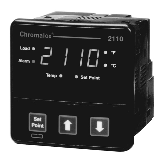
Chromalox
2110
Load
°F
Alarm
°C
(101.6)
Temp
Set Point
Point
(101.6)
Figure 3.3
Mounting Dimensions
Figure 3.4
Mounting the 2110
(92)
(10)
(90)
(102)
3.6
(92)
(92)
Holding
Tabs
Slots
Holding
Tabs
Front Collar
Rear Collar
Rear Collar
Mounting Screw
Good Wiring Practices
Separate wire into bundles — When planning the
system wiring, separate wiring into functionally similar
bundles, e.g.
• Power leads
• Sensor leads (if power leads must cross sensor
leads, they should cross at a 90° angle)
• Output signal lines
Separate sources of electrical noise — Locate all
sources of electrical noise in your system, and sepa-
rate these sources from the control system, e.g.
• Motors
• Contacts
• Solenoids
Electrical noise can affect the function of any control
system. When driving a contactor coil or other induc-
tive load, an appropriate rated AC snubber circuit is
recommended (Chromalox Part No. 0149-01305).
Connect before power is applied—Make all electrical
(12.7)
wiring connections to the back of the controller before
power is applied to the unit.
Comply with regulations.
All wiring practices must comply with local
regulations. Failure to do so could result in
damage to controller and/or personal injury or
death from electrical shock.
This instrument is intended for panel mounting and the
terminals must be enclosed within a panel. Use Nation-
al Electric Code (NEC) Class 1 wiring for all terminals
except the sensor terminals.
Check wiring decal — Check the wiring decal on the
side of the unit to verify the model number. The wiring
decal shows the wiring terminations. All wiring will be
connected to the terminals on the back of the instrument
case. Specific wiring instructions for different input and
output types are given in this section. See also Figure 3.5.
Additional information — For sensor wiring practices,
see "Sensor Input Wiring". For additional information
on good wiring practice, request IEEE Standard No.
518-1982 from IEEE, 345 East 47th St., New York, NY
10017 or www.ieee.org.
Sensor Input
Wiring
Output
Wiring
(S1, S2)
Figure 3.5
Wiring Terminal Identification
5
Alarm Wiring
COM
NO
NC
Instrument
Power Wiring
Output Wiring (R1, R3, V0, or S0)