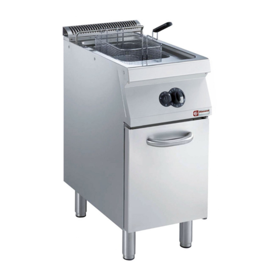
Diamond +7FRMH2FF5 Manuale - Pagina 7
Sfoglia online o scarica il pdf Manuale per Friggitrice Diamond +7FRMH2FF5. Diamond +7FRMH2FF5 15.
Anche per Diamond +7FRMH2FF5: Manuale d'uso (15 pagine), Manuale di avvio rapido (15 pagine)

5.1.4 GAS PRESSURE REGULATOR
If the gas pressure is higher than that specified or is difficult
to regulate (not stable), install a gas pressure regulator (ac-
cessory code 927225) in an easily accessed position ahead
of the appliance.
The pressure regulator should preferably be fitted horizon-
tally, to ensure the right outlet pressure:
• "1" connection side gas from mains.
• "2" pressure regulator;
• "3" connection side gas towards the appliance;
The arrow on the regulator (
direction.
NOTE! These models are designed and certified for use with
natural or propane gas. For natural gas, the pressure regulator
on the header is set to 8" w.c. (20mbar).
AUSTRALIA: the gas pressure regulator supplied with the
appliance must be fitted to the appliance inlet. Adjust the
test point pressure with one burner operating at maximum
setting as follow:
- 0.74 KPa for Natural gas
- 1.50 KPa for Propane gas
5.1.5
GAS
VALVE
ADJUSTMENT
• Remove the retaining screw from pressure point "B" and
connect the manometer tube.
• Feed the appliance with the correct nominal gas pres-
sure as specified in the corresponding paragraph 5.1.3.
• Start the fryer as indicated in the chapter "User Instruc-
tions".
• Turn gas valve "D" outlet pressure adjustment screw clock-
wise to increase the pressure and anticlockwise to de-
crease it, adjusting the pressure as specified in the noz-
zle table (table B).
5.1.6. CHECKING THE PRIMARY AIR SUPPLY
When the primary air supply is correctly adjusted, the flame
does not "float" with burner cold and there is no flareback
with burner hot.
• Undo screw "A" and position aerator "E" at distance "H"
given on the Table B, retighten screw "A" and seal with
paint (fig. 3A).
) shows the gas flow
2
3
1
OUTLET
PRESSURE
5.1.7. CHECKING THE PRIMARY AIR (tube version - fig. 3C)
To adjust, proceed as follows:
• Loosen fixing screw "C" and adjust bushing "D" at distance
"H" indicated in table "B" (fig. 3C).
• Tighten down fixing screw "C".
5.1.8. CONVERSION TO ANOTHER TYPE OF GAS
Table B "technical data/gas nozzles" gives the type of noz-
zles to be used when replacing those installed by the manu-
facturer (the number is stamped on the nozzle body). At the
end of the procedure, carry out the following check-list:
Check
• burner nozzle/s replacement
• correct adjustment of primary air supply to
burner/s
• pilot nozzle/s replacement
• minimum flame screw/s replacement
• correct adjustment pilot/s if necessary
• correct adjustment of supply pressure
(see technical data/nozzles table)
• apply sticker (supplied)
with data of new gas type used
5.1.8.1 REPLACING THE MAIN BURNER INJECTOR
(fig.3A)
• Loosen screw "A" and unscrew nozzle "C".
• Remove the nozzle and aerator (Fig.3A).
• Replace nozzle "C" with one suitable for the type of gas,
according to that given in table B.
• The nozzle diameter is given in hundredths of mm on the
nozzle body.
• Insert nozzle "C" in aerator "E" , then fit the two assembled
components in their position and screw the nozzle down.
5.1.8.2. REPLACEMENT OF THE MAIN BURNER
INJECTOR
(Tube version - fig. 3C)
• Unscrew nozzle "A" and replace it with one suitable for the
required type of gas, according to that given in table "B",
fig. 3C.
• Injector diameter is shown in hundredths of a millimeter on
the body.
• Tighten injector "A" fully down.
5.1.8.3. REPLACING THE PILOT BURNER NOZZLE
(for all versions - fig. 3B)
• Undo screw coupling "H" and replace nozzle "G" with one
suitable for the type of gas.
• The nozzle identification number is given on nozzle body.
• Refit coupling "H" and respective sealing washer.
Ok
23
