3Built RES126VX Istruzioni per l'installazione - Pagina 2
Sfoglia online o scarica il pdf Istruzioni per l'installazione per Telecomando 3Built RES126VX. 3Built RES126VX 3. Remote engine shut-off
Anche per 3Built RES126VX: Istruzioni per l'installazione (5 pagine), Manuale di avvio rapido (9 pagine)
INSTALLATION
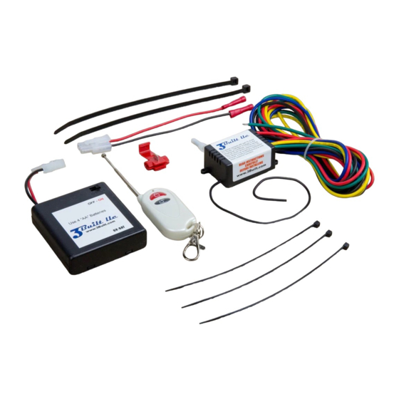
1) Find a suitable place to mount the Receiver (A). Position it so that it will stay dry and will not be damaged in case of
an accident. Attach with included double sided tape and two 11" Plastic Wire Ties (D).
2) If your vehicle has a 12-volt battery, then use the 12VDC Battery Cable (F). Attach BLACK wire ring terminal to
negative terminal of the battery. Do not attach RED wire until installation is complete.
If your vehicle does not have a 12-volt battery, then use the "AA" Battery Pack (E). Find a suitable place to mount the
"AA" Battery Pack (E). Position it so that it will stay dry and will not be damaged in case of an accident. Attach the
3M Dual Lock (similar to Velcro) to vehicle. Remove cover screw and install four AA batteries. Reinstall cover screw
and secure "AA" Battery Pack (E). Leave battery pack switched to OFF.
3) Plug Receiver Connector
Please make sure that the red wires line up on both sides of the connector.
4) Route the Black & Red wire from the Receiver
both wires about 1/4 inch. Crimp black wire on Receiver Module
same for the red wire. Use the 4" Plastic Wire Ties
necessary to keep wire safe. Improperly mounted wires can become damaged and short to the frame causing
damage to the vehicle and rider. Damage may include high heat and/or fire.
5) Choose either Normally Open or Normally Closed connection type. See image on next page.
5a) Normally Open Connection (8-amp max.)
Blue Wire – The wire will be attached to the vehicle's electrical system via a Crimp-on Wire Tap (H). The
location of the crimp is very important. The OEM RUN/STOP switch has two wires. One comes from the CDI
and the other goes to the vehicle's ground. The crimp must be placed between the CDI and the OEM Run/Stop
switch. Crimping the Blue Wire to an incorrect wire may damage the CDI or other electrical component. Use
caution and consult a professional if unsure.
Green Wire - Attach green wire to vehicle ground or negative side of battery.
Yellow Wire - Cut wire near Receiver
not be used.
5b) Normally Closed Connection (8-amp max.)
Blue & Yellow Wire – Identify the power wire from the OEM Run/Stop switch to the CDI. Cut the vehicle's wire
and attach the Receiver's Blue Wire to one end of the cut wire and the Receiver's Yellow Wire to the other end of
the cut wire. It does not matter which wire is attached to which side of the cut wire. It is very important to cut the
correct wire for proper operation. Incorrect wiring can damage the CDI or other electrical component. Use
caution and consult a professional if unsure.
Green Wire - Cut wire near Receiver
not be used.
©2023 3Built LLC
(C)
into the mating connector on 12VDC Battery Cable
(A)
(A)
and protect end of wire from making contact to anything. This wire will
(A)
and protect end of wire from making contact to anything. This wire will
to the Receiver Connector (C). Cut to appropriate length. Strip
(A)
to black wire on the Receiver Connector. Do the
(G)
to secure cable to vehicle. Additional wire ties may be
Page 2 of 3
(F)
or the "AA" Battery Pack (E).
May 11, 2023