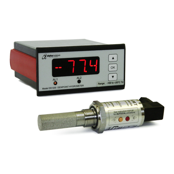
Alpha Moisture Systems DS1200-AMT Manuale di installazione, messa in servizio e funzionamento - Pagina 9
Sfoglia online o scarica il pdf Manuale di installazione, messa in servizio e funzionamento per Strumenti di misura Alpha Moisture Systems DS1200-AMT. Alpha Moisture Systems DS1200-AMT 18. Dewpoint analysis system

5)
Sample Pressure Gauge – This is not a critical part of the moisture measurement but may be required if Dew/Frost point
measurements are to be made at higher than atmospheric pressure.
6)
Measuring AMT Sensor.
7)
Sensor Holder.
8)
Desiccant Chamber – This item is required when the sampling is to be intermittent. When installed it prevents the ingress of
wet air to the sample system, while the sample is not flowing, improving the response time.
9)
Flow Control Valve – This can be a separate item or combined with the flow indicator.
10) Flow Indicator – The recommended sample flow is 2 to 3 SL/M.
11) Sample Exhaust – The exhaust can be vented to atmosphere or returned to the process line as discussed above.
6.3
Installing and Commissioning the Model AMT Transmitter
• It is advisable to carry out an initial purge routine of the sample loop, before installing the
sensor, in order to remove the possibility of sensor damage on start-up.
• Refer to the sample system schematic on page 6 of this manual and open the inlet isolation
valve slowly, until a small flow of air/gas at atmospheric pressure flows through the inlet
pipework to the sensor holder and exhausts through the sensor entry port of the sensor holder.
• Allow this purge to continue for about 15 to 20 minutes to remove any residual moisture
from the sample pipework and components.
• Close the inlet isolation valve, install the sensor into the sensor holder and ensure that the
sensor cable connector is correctly positioned, that the sealing cup is in place and the
retaining screw is screwed down securely to affect a weatherproof seal.
• Open the inlet valve slowly again and, by opening all valves after the sensor holder, allow a
low pressure purge through the whole sample system. (Note. If a closed by-pass loop is
installed, this section of the procedure is not possible).
• Set the required pressures and flows within the sample loop.
• This completes the installation and commissioning but, on initial start-up, it could take
several hours for the system to reach equilibrium, depending on the number and type of
components used in the sample loop.
• The instrument will now indicate the dewpoint of air/gas surrounding the sensor, at sensor
pressure and the analogue output will be giving a mA signal proportional to the indicated
dewpoint or other engineering units.
6.4
Operation
• The system is designed to operate continuously, with a minimum amount of operator input.
• It is, however, advisable to inspect the sample loop periodically to ensure that the required
pressures and flows are being maintained.
• The number and type of items employed in the sample loop will determine what, if any, other
routine checks should be made. If, for instance, a filter is used, the filter element should be
inspected periodically and changed when necessary.
• The instrument should not require any routine maintenance but if any malfunction is
suspected it is advisable to contact your local dealer.
• Should it be necessary, at any time or for whatever reason, to change either the instrument or
sensor, it should be noted that the components of the DS1200 system are fully and
completely interchangeable provided that the corresponding instrument/sensor range is
requested. The only adjustment necessary would be the alarm set points in the case of the
instrument.
• While the sensor should give several years operation, it is advisable to confirm the
calibration, from time to time, to ensure accurate operation of the system.
Page 6
