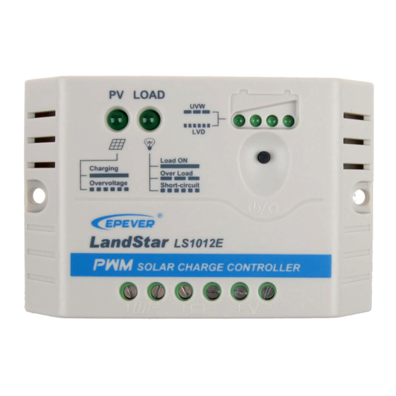
Epever LS1024E Manuale
Sfoglia online o scarica il pdf Manuale per Inverter Epever LS1024E. Epever LS1024E 2. Solar charge controller
Anche per Epever LS1024E: Manuale d'uso (20 pagine)

HUIZHOU EPEVER TECHNOLOGY CO., LTD.
※Thank you for selecting the LandStar E/EU series solar charge
controller. Please read this manual carefully before using the
product and pay attention to the safety information.
※Do not install this product in humid, salt spray, corrosion, greasy,
flammable, explosive, dust accumulative, or other severe
environments.
Solar Charge Controller
1. Safety Information
Read all the instructions in the manual before installation.
DO NOT disassemble or attempt to repair the controller.
Install an external fast-acting fuse or breaker as required.
Disconnect the solar module and fast-acting fuses/breakers near the battery
before installing or moving the controller.
Power connections must remain tight to avoid excessive heating from a
loose connection.
Only charge batteries that comply with the controller's parameters.
The battery connection may be a single battery or a bank of batteries.
Risk of electric shock! The PV and load can produce high voltages when the
controller is working.
2. Overview
The LandStar E/EU series controller is a PWM charge controller that adopts
the most advanced digital technique. It's an easy operation and cost-efficient
controller featured as:
3-Stage intelligent PWM charging: Bulk, Boost/Equalize, and Float
Support 3 charging options: Sealed, Gel, and Flooded
Battery status LED indicator indicates battery situation
Battery temperature compensation function
With humanized settings, the operation is more comfortable and convenient
The USB provides a power supply that can charge electronic equipment(LS
EU series only)
Battery type and load output can be set via the button
Extensive Electronic protection
3. Product Features
❶
Figure 1 Product Feature
❷
PV Terminals
❸
Battery Terminals
❹
Load Terminals
USB output interface
❺
(LS EU series only)
Mounting Hole Φ4.5
Connect the system in the order of ❶battery ❷ load ❸PV array
4. Wiring
following Figure 2-2," Schematic Wiring Diagram," and disconnect the system
in the reverse order❸❷❶.
NOTE: Do not connect the circuit breaker or fast-acting fuse while
wiring the controller. Ensure that the leads of "+" and "-" poles are
connected correctly.
NOTE: A fast-acting fuse whose current is 1.25 to 2 times the
controller's rated current must be installed on the battery side with a
distance from the battery not greater than 150 mm.
WARNING: The controller has no PV reverse connection protection;
please connect it correctly.
❻
❼
Load Switch Button
❽
Battery status LED indicator
Load status LED indicator
❾
Charging status LED
indicator
1
Tel: +86-752-3889706
Figure 2 Connection diagram
5. LED Indicators
1) Charging and load status indicator
Indicator
Color
Charging status
Green
LED indicator
Load status LED
Green
indicator
2) Battery status indicator
LED1
LED2
LED3
×
Slowly Flashing
×
Fast Flashing
Battery LED indicator status during voltage is up
○
○
○
○
○
○
Battery LED indicator status during voltage is down
○
○
○
○
○
×
NOTE:
① The above voltage values are measured in the 12V system at 25℃; please
double the values in the 24V system.
② "○" states LED indicator on; "×" states LED indicator off.
6. Operating
1) Load ON/OFF Setting
Press the button to control the load output when the controller is powered on.
2) Battery Type Setting
Operation:
Step 1: Enter the setting mode by pressing the button for 5s until the battery
status LEDs are flashing.
Step 2: Select the desired mode by pressing the button.
Step 3: The mode is saved automatically without any operation for 5S, and the
LED stops flashing. Battery Type Indicator shows as below:
LED1
LED2
○
×
○
○
○
○
NOTE: "○" states LED indicator on
Website: www.epever.com
Status
Instruction
On Solid
In Charging
OFF
No Charging
Battery Over
Fast Flashing
Voltage
On Solid
Load ON
OFF
Load OFF
Slowly Flashing
Overload
Fast Flashing
Load short circuit
LED4
Battery Status
×
×
Under voltage
×
×
Over-discharge
×
×
<13.4V
12.8V< U
bat
○
×
<14.1V
13.4V< U
bat
○
○
14.1V < U
○
×
<13.4V
12.8V<U
bat
×
×
<12.8V
12.4V<U
bat
×
×
<12.4V
U
bat
LED3
Battery type
×
Sealed(Default)
×
Gel
○
Flooded
"×" states LED indicator off
2
bat
