Axminster AWVSWL1200D Manuale d'uso - Pagina 8
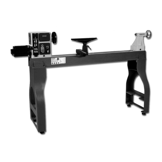
Sfoglia online o scarica il pdf Manuale d'uso per Tornio Axminster AWVSWL1200D. Axminster AWVSWL1200D 19. Woodturning lathe

clockwise direction, and tighten two set screws. Remove the faceplate by loosening two set
screws. Push in headstock spindle lock and use the provided rod in faceplate holes to
unthread the faceplate.
8. Headstock Indexing Hole: (L, Fig. 6) Thread indexing pin into the indexing hole making
sure that it locates in the spindle hole. There are 12 holes in the spindle 30° apart. There
are three holes in the headstock casting that accept the indexing pin. These holes are 20°
apart. The combination of holes will allow you to mark your work piece for evenly spaced
features.
CAUTION! Never start the lathe with the index pin engaged in the spindle!
9. Tool Rest Body Lock Handle: (M, Fig. 7) Locks the tool rest body in position. Unlock
handle to position the tool rest in any location along lathe bed. Tighten handle when
properly positioned.
10. Tool Rest Lock Handle: (N, Fig. 7 Locks the tool rest in position. Unlock the handle to
position tool rest at a specific angle, or height. Tighten handle when properly positioned.
11. Tailstock Lock Handle: (O, Fig. 8) Locks the tailstock in position. Unlock handle to
position the tool rest in any location along lathe bed. Tighten handle when properly
positioned.
12. Tailstock Quill Lock Handle: (P, Fig. 8) Locks the tailstock quill in position. Unlock
handle to position the quill. Tighten handle when properly positioned.
13. Tailstock Quill Handwheel: (Q, Fig. 8) Turn the handwheel to position the quill. The
tailstock quill lock handle must be loose to position quill.
14. Tailstock Live Center: (R, Fig. 8) Used for turning between centers. Quill taper is MT-2.
Remove live center by retracting the quill until live center loosens. Remove, or add different
tips to the live center by inserting the provided rod through
Fig.7
1. Disconnect the machine from the power source!
2. Loosen the locking handle (A, Fig. 9).
3. Lift up on the tensioning handle (B, Fig. 9) to remove tension from the poly v-belt.
You can now position the belt in the desired speed range. It is pictured in the low
speed pulley range. Note: The "High" speed range (330-3200) provides maximum
WOODLATHE MANUAL
Fig.8
8
