ABB ACS800 Multidrive Manuale hardware - Pagina 10
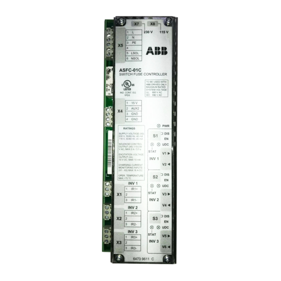
Sfoglia online o scarica il pdf Manuale hardware per Controllore ABB ACS800 Multidrive. ABB ACS800 Multidrive 20. Asfc switch fuse controller unit for frame r8i inverter modules

10
Inverter power switch-on sequence
The terms and designations used in the table below refer to the diagram in section
Connections of the inverter power
1.
2.
3.
Inverter power switch-off sequence
The terms and designations used in the table below refer to section
the inverter power
1.
2.
Hardware description
Operation
User turns switch fuse
handle to 1 (On)
position.
Inverter capacitor
bank charges.
ASFC unit detects that
charging is completed:
charging current
< 0.7 A and UDC1
signal received
(U
> 80%
DC
acknowledgement
from Inverter 1).
supply.
Operation
User turns switch fuse
handle to 0 (off)
position.
Inverter capacitor bank
discharges.
supply.
What happens
Secondary contacts of switch fuse operate. Locking mechanism
keeps spring operated primary contacts open.
Secondary contact 43-44 connects power supply to ASFC unit.
ASFC unit keeps switch fuse solenoid circuit open at this stage.
Secondary contacts 1-2 and 3-4 connect DC bus voltage to inverter
input connectors throughASFC unit and charging resistors R1 and
R2.
"INV1 STAT" and "PWR" LEDs on.
ASFC unit monitors status of charging by measuring current, and
monitoring inverter UDC1 signal through fibre optic link V2.
"INV1 STAT" and "PWR" LEDs on.
ASFC unit gives operating voltage (pulse) for solenoid. Solenoid
releases locking mechanism of switch fuse primary contacts.
Primary contacts operate, inverter is connected to drive DC bus.
Contact 13-14 indicates "switch fuse on" state to ASFC unit.
ASFC unit sends INV1 EN signal to inverter Main Circuit Interface
Board (AINT) enabling inverter start.
Contact 21-22 disconnects solenoid control circuit.
"INV UDC" LED on.
What happens
Auxiliary contacts of switch fuse operate. Contact 13-14 indicates
"switch fuse open" state to ASFC unit.
ASFC inactivates INV1 EN signal. Inverter 1 stops (if running).
After 5 to 20 ms delay, main contacts 1-2 and 3-4 of switch fuse
open disconnecting inverter from drive DC bus.
Contact 43-44 switches off power supply of ASFC unit.
No LEDs on.
Inverter DC voltage decreases to zero gradually.
No LEDs on.
Connections of
