FHF Aiza AXL05 Manuale - Pagina 2
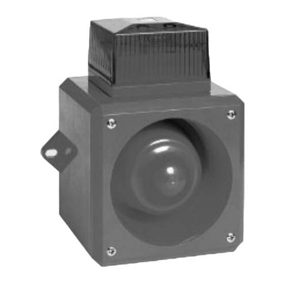
Sfoglia online o scarica il pdf Manuale per Attrezzatura marina FHF Aiza AXL05. FHF Aiza AXL05 6. Sounder and sounder-strobe-combination
Installation
The sounder or combined sounder strobe units can be
affixed to most surfaces using screws through the exter-
nal mounting lugs. A 20 mm gland entry is provided for
the supply cable. The cable and gland must be fitted in
accordance with the national and local regulations. It is
not necessary to earth the sounder circuitry but earth
tags should be used if earth continuity of conduit or
cable sheathing needs to be maintained.
Supply input
Ensure that the supply is correct for the voltage rating of
the sounder or combined sounder strobe being installed.
Ensure that the supply is OFF before making any con-
nection and wire only in accordance with the terminal
label detail.
Sound selection
Ensure the supply is OFF before proceeding. All dc and
ac units have selectable alarm sounds (see table below
for details) and are selectable by means of the 5 way DIL
switches SW1 for the first stage and SW2 for the second
stage. For dc units the second sound is made available
upon the application of a third wire connected to terminal
TB 1/3 as shown in Fig. 1 while still connected to termi-
nal TB 1/2. Alternatively first and second stage sound
signals can be generated by supply reversal at terminals
Technical Data AX05
Housing
Colour
Insulation class
Protection degree
Cable gland
Volume
Signals
Temperature range
Operation
Storage
Weight
Operating voltage
Connecting terminals
Technical Data AXL05
Housing
Colour
Insulation class
Protection degree
Cable gland
Volume
Signals
Temperature range
Operation
Storage
Weight
Operating voltage
Connecting terminals
Flash power
Cap colours
2
Polycarbonate
Red, similar to RAL 2002
II
IP 65 acc. to IEC 60529
intended for M20 x 1.5 or Self-sealing grommet
approx. 97-110 dB(A) (depending on signal tone)
32 different signal tones (see diagrams), 2nd stage can be turned on externally
-25 °C to +55 °C
-40 °C to +70 °C
AC 0.7 kg / DC 0.6 kg
24 VDC, 115 VAC, 230 VAC
Clamping capacity 2.5 mm
Polycarbonate
Red, similar to RAL 2002
II
IP 65 acc. to IEC 60529
intended for M20 x 1.5 or Self-sealing grommet
approx. 97-110 dB(A) (depending on signal tone)
32 different signal tones (see diagrams), 2nd stage can be turned on externally
-25 °C to +55 °C
-40 °C to +70 °C
AC 1 kg / DC 0.9 kg
24 VDC, 115 VAC, 230 VAC
Clamping capacity 2.5 mm
5 J
red, yellow, green, blue, clear
TB1/3 and TB1/4, see Fig. 2. For ac units the second
stage is available upon the application of a third wire L to
TB3, see Fig. 3.
Mounting
The AX05 / AXL05 series alarm units are mounted to
a wall or bulkhead of suitable material using the lugs
projecting from the side of the case. The lugs are bored
8 mm clearance on 153 mm centres. The recommended
length of fixing screws is 25 mm. To maintain the integrity
of the weather seal, the cable entry must be via a suitable
sealed gland.
Recycling
The device may be completely recycled as electronic
waste. When the device is disassembled, plastics,
metals and electronics are to be disposed of separately.
EM -Directive
The device complies with the requirements of the
new EMC-directive 2004/108/EC and the low voltage
directive 2006/95/EC.
The conformity with the above directives is confirmed
by the CE sign.
2
solid conductor / 1.5 mm
2
solid conductor / 1.5 mm
2
stranded conductor
2
stranded conductor