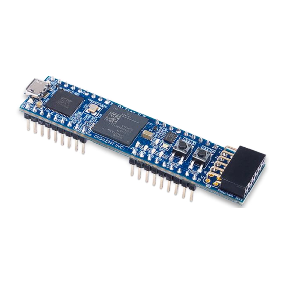
Digilent PLTW S7 Manuale di riferimento - Pagina 5
Sfoglia online o scarica il pdf Manuale di riferimento per Scheda madre Digilent PLTW S7. Digilent PLTW S7 11.

PLTW S7 Reference Manual
2.2
Quad-SPI Configuration
Since the FPGA's memory on the PLTW S7 is volatile, it relies on the Quad-SPI flash memory to store the
configuration between power cycles. This configuration mode is called Master SPI. The blank FPGA takes the role
of master and reads the configuration file out of the flash device upon power-up. To that effect, a configuration file
needs to first be written to the flash. When programming a non-volatile flash device, a bitstream file is transferred
to the flash in a two-step process. First, the FPGA is programmed with a circuit that can program flash devices, and
then data is transferred to the flash device via the FPGA circuit (this complexity is hidden from the user by the
Xilinx tools). This is called indirect programming. After the flash device has been programmed, it will automatically
configure the FPGA at any subsequent power-on event. Programming files stored in the flash device will remain
until they are overwritten, regardless of power-cycle events.
Quad-SPI programming can be performed using Vivado's Hardware Manager.
3
Quad-SPI Flash
FPGA Configuration files can be written to the Quad-SPI Flash (Macronix part number MX25L3233F). The FPGA will
automatically read a configuration file from this device at power on. A Spartan-7 25T configuration file requires
9,935,224 bits of memory, leaving about 69% of the flash device (or ~2.8 MB) available for user data. A common
use for this extra memory is to store MicroBlaze programs too big to fit in the onboard block memory. These
programs are then loaded and executed using a smaller bootloader program that can fit in the block memory. It is
possible to automatically generate this bootloader, roll it into the bitstream, and then program the bitstream and
large MicroBlaze program into the Quad SPI Flash using Xilinx SDK.
The contents of the memory can be manipulated by issuing certain commands on the SPI bus. The implementation
of this protocol is outside the scope of this document. Xilinx's AXI Quad SPI IP core can be used to read/write the
flash in a MicroBlaze design. Refer to
to
Macronix's datasheet
for the flash device to learn how to implement a custom controller. All signals in the SPI
bus are general-purpose user I/O pins after FPGA configuration and can be used like any other FPGA I/O.
Copyright Digilent, Inc. All rights reserved.
Other product and company names mentioned may be trademarks of their respective owners.
Xilinx's product guide
for this core to learn more about using it, or
Figure 3.1. Flash interface.
Page 5 of 11
