Digilent Basys 2 Manuale di riferimento - Pagina 10
Sfoglia online o scarica il pdf Manuale di riferimento per Hardware del computer Digilent Basys 2. Digilent Basys 2 12. Fpga board

Basys2™ FPGA Board Reference Manual
can be derived. Timings for sync pulse width and front and back porch intervals (porch intervals are the pre- and
post-sync pulse times during which information cannot be displayed) are based on observations taken from actual
VGA displays.
A VGA controller circuit decodes the output of a horizontal-sync counter driven by the pixel clock to generate HS
signal timings. This counter can be used to locate any pixel location on a given row. Likewise, the output of a
vertical-sync counter that increments with each HS pulse can be used to generate VS signal timings, and this
counter can be used to locate any given row. These two continually running counters can be used to form an
address into video RAM. No time relationship between the onset of the HS pulse and the onset of the VS pulse is
specified, so the designer can arrange the counters to easily form video RAM addresses, or to minimize decoding
logic for sync pulse generation.
7
Expansion Connectors (6-pin Headers)
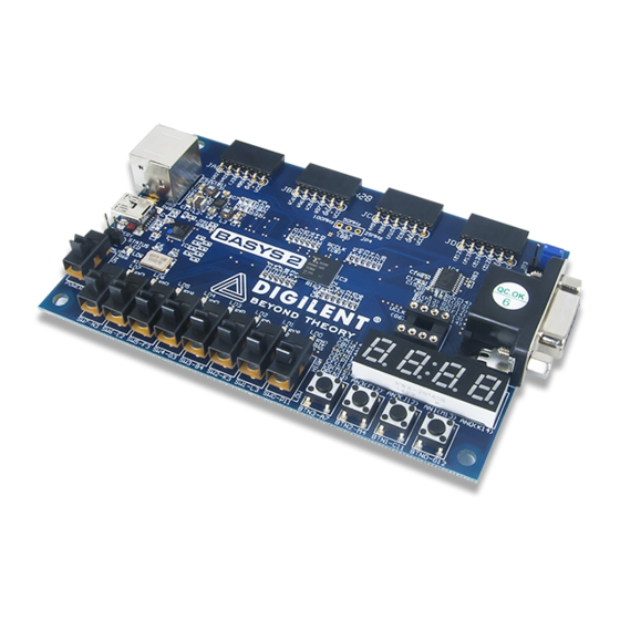
The Basys 2 board provides four 6-pin peripheral module connectors. Each connector provides Vdd, GND, and four
unique FPGA signals. Several 6-pin module boards that can attach to this connector are available from Digilent,
including A/D converters, speaker amplifiers, microphones, H-bridge amplifiers, etc. Please see
www.digilentinc.com
for more information.
Copyright Digilent, Inc. All rights reserved.
Other product and company names mentioned may be trademarks of their respective owners.
Short-circuit protection
resistors
B2
A3
J3
B5
ESD protection
Spartan 3E
diodes
FPGA
C6
1
B6
2
C5
3
B7
4
A9
1
B9
2
A10
3
C9
4
C12
1
A13
2
C13
3
D12
4
Figure 18. Basys 2 Pmod port circuits.
1
2
6-pin
3
header
4
JA
5
6
3.3V
6-pin
header
JB
6-pin
header
JC
6-pin
header
JD
Page 10 of 12
