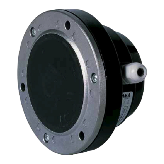
FIAMA SM85.ATEX Manuale di uso e manutenzione - Pagina 4
Sfoglia online o scarica il pdf Manuale di uso e manutenzione per Interruttore FIAMA SM85.ATEX. FIAMA SM85.ATEX 7. Membrane level switch

ATEX level switch
Interconnecting cables
The low values of voltage and tension which are present in the instrinsic safety circuit allow the use of cables
which are normally used for field instrumentation, as long as the capacity and inductance of these is correctly
taken into account in the calcultations regarding system safety. The cable parameters are rarely a problem for the
distance of the field devices, especially when galvanic separation barriers are used.
Resistive circuits
A circuit is considered resistive when the reactive parts,
inductance and capacity, are null or negligible, as is the case of
this analysis.
The energy which can be released by a circuit of this type
depends essentially upon the voltage V that powers it and by the
current limitation which is due to the presence of the resistor R.
In this case it is not easy to correlate the value of the minimum
ignition energy MIE (Minimum Ignition Energy), with the circuit
characteristics which generate the spark.
The ignition curves for resistive circuits are indicated in the side
graph.
The graph shows the ignition curves of the gas groups which are
considered in the various norms. Observing the curves, the lower
the open circuit voltage Voc, the higher the power that can be
used in safety. This characteristic allows the process
instrumentation, which operates at voltages in the 20-30V range,
to be used in applications of intrinsic safety.
Intrinsic safety loop coordination
In the coordination, the following relations must be verified:
where:
•
Uo: maximum output voltage (peak AC or DC) which can
be supplied by an intrinsic safety barrier which is in open
circuit and powered by the primary voltage Um
•
Io: maximum current (peak AC or DC) which can be
supplied by an intrinsic safety barrier which is in short-
circuit
•
Po: maximum electrical power which can be supplied by an intrinsic safety barrier
•
Co: maximum capacity which can be connected to the intrinsic safety barrier
•
Lo: maximum inductance which can be connected to the intrinsic safety
•
Ui: maximum voltage (peak AC or DC) which can be applied to the intrinsic safety sensor in the danger
zone
•
Ii: maximum current (peak AC or DC) which can be applied to the intrinsic safety sensor in the danger
zone
•
Pi: maximum input power which can be applied to the intrinsic safety sensor in the danger zone
•
Ci: total equivalent internal capacitance of the intrinsic safety apparatus
•
Li: total equivalent internal inductance of the intrinsic safety apparatus
•
Cc: cable capacitance [F/m]
•
Li: cable inductance [H/m].
Date: 07/2018
Uo ≤ Ui
Io ≤ Ii
Po ≤ Pi
Ci+Cc ≤ Co
Li+Lc ≤ Lo
SM85.ATEX_ing_rev05.doc
SM85.ATEX
page 4 of 6
