digimess HY3020 Manuale di istruzioni per l'uso - Pagina 6
Sfoglia online o scarica il pdf Manuale di istruzioni per l'uso per Alimentazione digimess HY3020. digimess HY3020 14.

3.0
Operating instructions
3.1
Mains input
The mains input connector is located on the rear of the unit. Before connecting to the mains supply the user
should verfy that the unit is set to the correct voltage for the country of use. The mains voltage is set by the
external mains voltage selector switch located on the rear of the unit.
3.2
Mains input fuse
The mains fuse is located on the rear of the unit. The correct fuse for each supply voltage is as follows :
Model
HY3003
HY3003-2
HY3003-3
HY3010
HY3020
3.3
Power on/off
The mains power to the unit is switched on and off using the POWER on/off pushbutton.
3.4
Voltage and current display
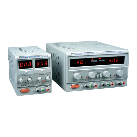
Single output models - HY3003, HY3010 and HY3020 feature independent displays for both output voltage
and output current. Multiple output models - HY3003-2 and HY3003-3 feature a single display for each
adjustable output and can be switched to display either output voltage or output current.
3.5
Single output unit or multple output unit in Independent mode
For multple output units, Independent mode is set by selecting the two Tracking switches to the Independent
postion. The output voltage is adjusted to the desired value using both the Coarse and Fine (if fitted) Voltage
controls. The output current level is adjusted to the desired value usng both the Coarse and Fine (if fitted)
Current controls. If the output current exceeds the set current value the power supply will limit the output
current to the set value.
3.6
Multiple output unit in Series mode
Multple output units can be set to Series mode by selecting the two Tracking switches to the Series position.
The output voltage is set by the Master Voltage control and the Slave output will track the Master output
voltage level. Current adjustment is independent and requires the Slave output current setting to be high
enough otherwise tracking will not occur as the Slave output will current limit. In this mode the +ve terminal
of the Slave output should be connected with a thick wire to the –ve output terminal of the Master to avoid
damage to the unit in the event of an overload. In this mode the maximum output voltage is the sum of the
Master and Slave output voltages.
6
110Vac
T4A 250V
T6.3A 250V
T6.3A 250V
T10A 250V
T15A 250V
220Vac
T2A 250V
T3.15A 250V
T3.15A 250V
T5A 250V
T8A 250V
