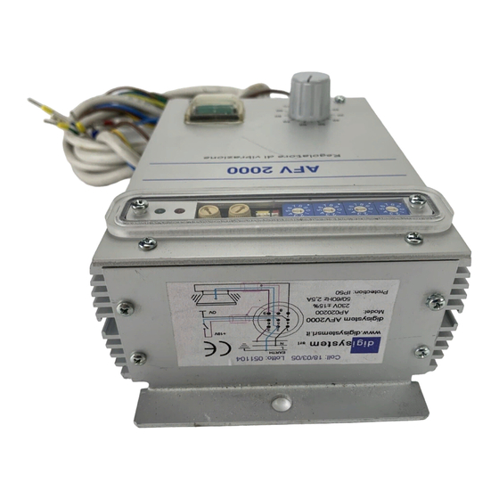
DIGISYSTEM AP00010G Manuale di istruzioni - Pagina 6
Sfoglia online o scarica il pdf Manuale di istruzioni per Alimentazione DIGISYSTEM AP00010G. DIGISYSTEM AP00010G 9.

STARTUP
• Verify that mains breaker is in OFF position
• Put the voltage reference at about 20%
• Verify switch SW2 (red) lever status (if is up the power supply will start as soon as
supplied, if is down the external start command is required)
• Verify if the trimmer P1 (min) is rotated fully counterclockwise and if the trimmer
P2 (max) is rotated fully clockwise
• Verify that all connections are fastened
• Put rotating switches SW1 at 050.0 if a output frequency of 050.0 Hz is required
• Connect the mains breaker (230 Vac)
• If start command is active the vibrator will be supplied at the frequency selected
with rotating switches SW1 (50 Hz) and at the voltage defined from the voltage
reference.
In practice, the search of the resonance frequency is made by checking the effects on the
product feeding obtained by regulating the selectors SW1 values.
Usually the resonance frequency is not too far from the rated (for a 50 Hz vibrator should be
between 45 and 55 Hz), but also a little frequency change will determine a significant speed change.
Than, proceed by further guesses until you find the position of the rotating switches SW1
which determines the resonance condition.
Then, after having reached it increase (or decrease) the reference value to obtain the required
vibration level.
During the research stage it is suitable that the reference voltage remains at 20% of the
end of scale (about 1 volt).
If, increasing the reference value, the green led DL1 switches off whereas the red one DL2
switches on and the vibrator stops, it means that the device is in overload; decrease the reference
value and the power supply will automatically reset the overload condition.
Downloaded from StockCheck.com
6
