FiberHome AN5506-04-F Manuale d'uso - Pagina 2
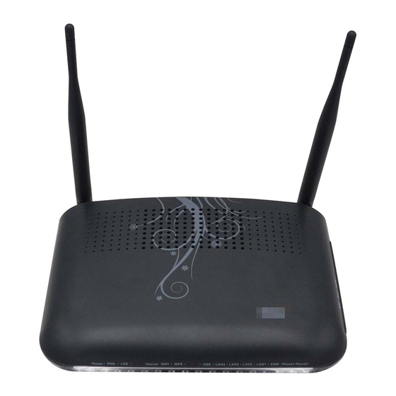
Sfoglia online o scarica il pdf Manuale d'uso per Hardware di rete FiberHome AN5506-04-F. FiberHome AN5506-04-F 2. Gpon optical network unit
Logging into Web Configuration GUI
Step 1
Set the IP address and subnet mask of the computer.
Select the Obtain an IP address automatically mode.
Set the static IP: The IP address should be in the same network segment as the
management IP address of the AN5506-04-F (recommended).
IP address: 192.168.1.X (X is a decimal integer between 2 and 253)
Subnet mask : 255.255.255.0
Step 2
Enter http://192.168.1.1 in the address bar of the browser and press Enter. The user login dialog box
appears.
!
Note
:
The factory default management IP address and the subnet mask of the AN5506-04-F are:
IP Address: 192 168 1 1
.
. .
Subnet mask: 255 255 255 0
.
.
.
Step 3 Enter the user name and password in the login dialog box. After being verified, you can
access the Web configuration GUI.
!
Note:
The factory default username and password of the AN5506-04-F are:
Username: admin
Password: admin
Configuring Internet Access Ser vice
Step 1
Select
Network
in the navigation bar and click
BroadBand Settings
in the link bar to
open the configuration GUI for the Internet access ser vice.
Step 2
Select
PPPoE
(recommended) for the WAN connection type.
Step 3
Enter parameters of the PPPoE mode.
!
Note:
Parameters of the PPPOE mode includes:
User Name: Enter the user name provided by the ISP.
Password: Enter the password provided by the ISP.
Verify Password: Enter the password for a second time to verify whether the
passwords entered at the two times are the same.
Operation Mode: Select either the Keep Alive mode or the Manual mode in the
pulldown menu.
4
"
",
。
Configuring WIFI Wireless Access Ser vice
Step 1
Select
Network
in the navigation bar and click
Wlan Settings
in the link bar to open
the configuration GUI for the wireless access ser vice.
Step 2
Select
RADIO ON
to enable the WLAN ser vice.
Step
3
Select
802.11
b/g/n for the
Network Mode
.
Step 4
Select
AutoSelect
or
channel1
to
channel 14
for the
Frequency (Channel)
in the
drop-down list
.
Note: If the connection fails after a channel is selected, another AP equipment
!
nearby is watching this channel. Please retry the connection after changing to
another channel.
Step
6 Click
Apply
to save the configured data.
Configuring LAN Ser vice
Step
1
Select
Network
→
LAN Settings
→
LAN Settings
in the navigation bar. In the screen
that is opened, you can configure the LAN parameter.
Step 2
Enter the LAN-side IP address 192.168.1.1 of the AN5506-04-F.
Step 3
Enter the LAN-side subnet mask 255.255.255.0 of the AN5506-04-F.
4
"
"
,
。
Step 5
Select
Network
→
DHCP Ser ve
r →
DHCP Ser vice
in the navigation bar. In the screen
that is opened, you can configure the DHCP ser ver parameters.
Step 6
Select
Sever
for the DHCP type and configure DHCP ser ver parameters.
!
Note:
Parameters to be configured of the DHCP server include
:
Start IP Address: Enter the starting value 192.168.1.2 of the IP addresses
automatically allocated by the DHCP server.
End IP Address: Enter the ending value 192.168.1.253 of the IP addresses
automatically allocated by the DHCP server.
Subnet Mask: Enter the subnet mask 255.255.255.0 designated by the DHCP server.
Primary DNS Server: Enter the IP address 192.168.1.1 of the primary DNS
server of the DHCP.
Default Gateway: Enter the default gateway IP address 192.168.1.1 of the DHCP.
Step 7
Click
Apply
to save the settings.
Configuring ONU Authorization
Step 1
Select
Network
→
Authentication Settings
→
OLT Authentication
in the navigation bar.
In the screen that is opened, modify related parameters of ONU authentication.
Step 2
Configure Logic SN and password of SN authentication
.
Step 3
Click
Apply
to save the settings.
Step 4
Configure the password of password authentication.
Step 5
Click
Apply
to save the settings.
No te : Th e SN authentication and password authentication can be separately
!
co nf ig ur ed a n d applied.
FAQs
FAQ1: All indicator LEDs are extinguished after power-on.
1.
Check whether the power cable is correctly connected;
2.
Check whether the power supply and the power adapter are normal;
3.
Check whether the power switch on the equipment's rear panel is in the ON position.
FAQ2: The equipment fails to work .
1.
If the equipment works abnormally, check whether the power is connected normally or
the voltage is not within specifications;
2.
If the equipment is overheated, check the ventilation. Make sure the equipment is not
exposed to direct sunshine or is near the heat source.
FAQ3:
LOS
blinks
The
indicator LED
.
1.
Check the received optical power levels with an optical power meter. Excessively low
receive optical power may indicate the fiber is faulty;
2.
Check whether the optical fiber is connected normally to the appropriate interface;
3.
Check whether the Rx optical power of the ONU crosses the normal optical power range
(overlow or overhigh);
4.
Check whether the ONT module is aged or damaged;
5.
Check whether the equipment at the central office end is operating normally.
:
FAQ4 The LAN indicator LED is extinguished.
1.
Check if the network cable is damaged or incorrectly connected;
2.
Check if the wiring color-coding scheme of the network cable is incorrect. If incorrect,
replace the original network cable with a standard CAT-5 twisted-pair network cable.
3.
Check if the network cable crosses the allowed range of 100 meters.
FAQ5:
The WIFI indicator LED is extinguished.
1.
Check if the wireless terminal is connected;
2.
Check if the wireless function is disabled.
FAQ6:
Logging into the
Web page
failed.
1.
Check the network card configuration, browser version of the user's computer ;
2.
Check whether the IP address of the user's computer is correctly configured.