Digital Devices Octopus Net mini ITX Manuale - Pagina 6
Sfoglia online o scarica il pdf Manuale per Apparecchiature di registrazione Digital Devices Octopus Net mini ITX. Digital Devices Octopus Net mini ITX 8.

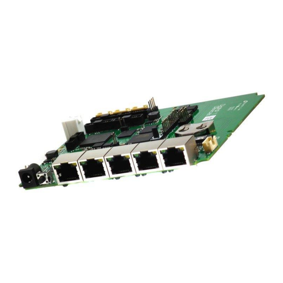
5. Description of the mainboard
1)
E/A Switch with LED
2)
Status LED 1 and 2
3)
Pin header for power switch and power LED (See Page 8)
4)
Molex P4 socket for internal power supply
5-8)
Power Port 1-4 (See info below)
9-12)
Connection extension TAB1-TAB4
13)
Status LEDs, for production purposes
14)
Connection Max S8/SX8, Max M4 or Max A8/A8I PCIe (GT Link Port- no DuoFlex possible)
15)
Power Port 5
16)
Socket for external power supply unit
17)
Reset-Button
18)
5 Port Gigabit Switch
Info: When installing a Max card without fan control (No fan socket on the Max Series card), the
power ports 1+2 (Fig.3) are intended for the connection of fans and no extensions can be
operated on them. However, if a Max board with fan control (Fan socket available on the Max
Series Card) is used and a fan is connected to it, power ports 1+2 (fig.3) can be used normally.
Addition to the Octopus Net manual - Octopus NET Mini ITX
(Abb. 3)
6
24. Mai 2017
