Siemens SIMATIC ET 200AL Manuale - Pagina 15

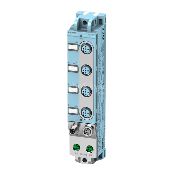
Sfoglia online o scarica il pdf Manuale per Apparecchiature industriali Siemens SIMATIC ET 200AL. Siemens SIMATIC ET 200AL 26. 10-link digital output module dq 8x24vdc/2a 8xm12
Anche per Siemens SIMATIC ET 200AL: Manuale (38 pagine), Manuale (50 pagine), Manuale (38 pagine), Manuale (32 pagine), Manuale (37 pagine), Manuale dell'apparecchiatura (46 pagine), Manuale dell'apparecchiatura (28 pagine), Manuale dell'apparecchiatura (27 pagine), Manuale (25 pagine)

Siemens SIMATIC ET 200AL Manuale
Wiring

3.2 Pin assignment

3.2
Pin assignment
Pin assignment of the sockets for digital inputs/digital outputs
The table below shows the pin assignments of the 8 sockets for the connection of the digital
inputs/digital outputs.
Table 3- 1
Pin
1
2
3
4
5
Pin assignment of the connector for IO-Link
The following table shows the pin assignment of the connector for the IO-Link.
Table 3- 2
Pin
1
2
3
5
Note
Note that the module can only be supplied with a protective low voltage according to the
standard SELV/PELV.
14
Pin assignment for digital inputs/digital outputs
Assignment
X10 to X17 - sockets for digital inputs/outputs
24 V encoder supply 2U
(derived from 2L+ switched)
Input/output signal DIQ
Ground 2M
Input/output signal DIQ
Functional earth FE
Pin assignment of the IO-Link interface
Assignment
X35
1L+
2L+
Ground 1M
4
Switching and communication cable (C/Q)
Ground 2M
IO-Link digital input/digital output module DIQ 16x24VDC/0,5A 8xM12 (6ES7143-5AH00-0BL0)
S
: Connector X10
1
: Connector X11
3
: Connector X12
5
: Connector X13
7
: Connector X14
9
: Connector X15
11
: Connector X16
13
: Connector X17
15
: Connector X10
0
: Connector X11
2
: Connector X12
4
: Connector X13
6
: Connector X14
8
: Connector X15
10
: Connector X16
12
: Connector X17
14
Front view of the sockets
X10, X12, X14,
X11, X13, X15,
X16
Front view of the connector (Port Class
B)
Equipment Manual, 08/2021, A5E47926885-AB
X17