Siemens SINAMICS G120 Istruzioni per l'uso compatte - Pagina 28

Sfoglia online o scarica il pdf Istruzioni per l'uso compatte per Apparecchiature industriali Siemens SINAMICS G120. Siemens SINAMICS G120 32. Using blocksize converters in marine applications
Anche per Siemens SINAMICS G120: Come iniziare (46 pagine), Manuale di istruzioni per l'uso (32 pagine), Come iniziare (30 pagine), Istruzioni per l'installazione dell'hardware (2 pagine), Istruzioni per l'installazione e manuale d'uso (2 pagine), Istruzioni per l'installazione (2 pagine), Istruzioni per l'installazione (2 pagine), Manuale (42 pagine), Come iniziare (50 pagine), Manuale del dispositivo (34 pagine), Manuale di installazione rapida (2 pagine), Descrizione dell'applicazione (50 pagine), Istruzioni per l'uso compatte (2 pagine), Manuale (31 pagine), Manuale delle applicazioni (34 pagine), Istruzioni per l'uso compatte (2 pagine), Istruzioni per l'uso compatte (2 pagine)
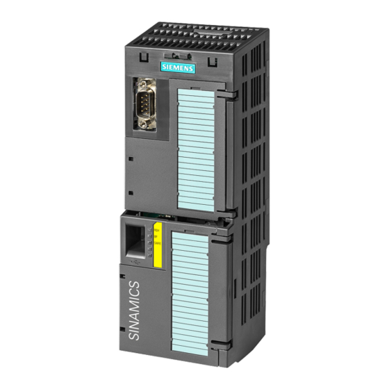
Siemens SINAMICS G120 Istruzioni per l'uso compatte
Commissioning

4.4 Frequently required parameters

Status word 1 (ZSW1), PZD send word 1 (word: p2051[0], bits: p2080[0] ... p2080[15])
Bit
Meaning
0
1 = Ready to start
1
1 = Ready
2
1 = Operation enabled
3
1 = Fault active
4
1 = OFF2 inactive
5
1 = OFF3 inactive
6
1 = Closing lockout active
7
1 = Alarm active
8
1 = Speed deviation within the
tolerance range
9
1 = Master control requested
10
1 = Comparison speed reached
or exceeded
11
1 = torque limit reached
12
1 = Holding brake open
13
0 = Alarm, motor overtempera-
ture
14
1 = Motor rotates clockwise
0 = Motor rotates counter-
clockwise
15
0 = Alarm, inverter thermal
overload
4.4
Frequently required parameters
Parameter
Explanation
p0015
Macro drive unit
Set defaults for inputs and outputs via a macro.
r0018
Control Unit firmware version
p0096
Application class
p0100
IEC/NEMA mot stds
p0304
Rated motor voltage [V]
p0305
Rated motor current [A]
p0307
Rated motor power [kW] or [hp]
p0310
Rated motor frequency [Hz]
p0311
Rated motor speed [rpm]
28
Comments
Power supply switched on; electronics initialized; pulses locked.
Motor is switched on (ON/OFF1 = 1), no fault is active. With the command "Enable
operation" (STW1.3), the inverter switches on the motor.
Motor follows setpoint. See control word 1, bit 3.
The inverter has a fault. Acknowledge fault using STW1.7.
Coast down to standstill is not active.
Quick stop is not active.
It is only possible to switch on the motor after an OFF1 followed by ON.
Motor remains switched on; no acknowledgement is necessary.
Setpoint / actual value deviation within the tolerance range.
The automation system is requested to accept the inverter control.
Speed is greater than or equal to the corresponding maximum speed.
Comparison value for current or torque has been reached or exceeded.
Signal to open and close a motor holding brake.
--
Internal inverter actual value > 0
Internal inverter actual value < 0
0: Expert
1: Standard Drive Control
2: Dynamic Drive Control
0: Europe 50 [Hz]
1: NEMA motor (60 Hz, US units)
2: NEMA motor (60 Hz, SI units)
CU240B-2 and CU240E-2 Control Units
Compact Operating Instructions, 04/2015, A5E35792002B AA