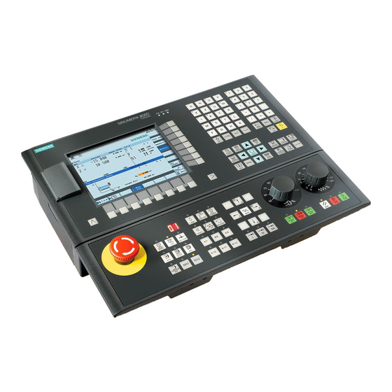
Siemens SINUMERIK 808D Istruzioni
Sfoglia online o scarica il pdf Istruzioni per Apparecchiature industriali Siemens SINUMERIK 808D. Siemens SINUMERIK 808D 2. Connecting with v60 driver
Anche per Siemens SINUMERIK 808D: Manuale di istruzioni per l'uso (34 pagine), Manuale di servizio (46 pagine), Manuale di servizio (48 pagine), Manuale di installazione (48 pagine)

808D set point cable X51~ ~ ~ ~ X53 connecting with V60 driver instructions
1. 808D PPU interface X51~X53 is defined as axis pulse interface, the standard configuration is
SINAMCIS V60 drive.
2. The detail interface signal for Standard configuration SINAMCIS V60 drive as below:
808D PPU
symbol(colour)
X51~X53 port
1
PULSE+ (green) Positive pulse(NC output signal)
9
PULSE- (yellow)
2
DIR+
10
DIR-
3
ENA+
11
ENA-
65
RST
6
(white/green)
7
M24
ALM1
5
(red/blue)
15
ALM2
8
RDY1 (black)
14
RDY2 (purple)
No.:2012-12-001
( Taking a milling machine for an example)
The description of signal
Negative pulse(NC output signal)
(gray)
DIRECTION +(NC output signal)
(pink)
DIRECTION -(NC output signal)
(brown)
Pulse enable+(NC output signal)
(white)
Pulse enable-(NC output signal)
servo enable(NC output signal)
Alarm Reset(NC output signal)
Servo enable and ALARM RESET
(red)
Ground
Power from the pin 1 of X200,
+24V output
Alarm, from drive side(NC input
(blue)
signal)
Power from the pin 1 of X200,
+24V output
Drive ready signal ( NC input
signal)
I DT SNC M3S
V60 port /pin
Remark
X5 / pin1
5V signal
X5 / pin2
5V signal
X5 / pin3
5V signal
X5 / pin4
5V signal
X5 / pin5
5V signal
X5 / pin6
5V signal
+24V=drive
X6 / pin1
enable
0V=drive disable
X6 / pin2
+ 24V high active
X6 / pin3
X6 / pin4
When alarm is
X6 / pin5
triggered,ALM1,
ALM2 close
X6 / pin6
drive is ready, the
X6 / pin7
line close.
