Installing the mechanical limit switch module
To install the mechanical limit switch module, proceed as follows:
1. Remove all electrical connects in the motherboard.
2. Loosen both fixing screws on the motherboard.
3. Snap out the motherboard by carefully bending the four holders.
4. Insert the mechanical limit switch module from above until it reaches the upper circuit
5. Push the mechanical limit switch module in the circuit board rail of the rack approx. 3 mm
6. Screw the special screw through the mechanical limit switch module into the axle of the
7. The insulating cover is locate above the mechanical limit switch module. Place the
8. Lay the insulating cover on the mechanical limit switch module by carefully bending the
9. Snap the motherboard into the four holders.
10. Secure the motherboard with both fixing screws again.
11. Reestablish all electrical connections between the motherboard and the option modules.
12. Fix the module cover included with the delivery with both screws. Do not use the standard
13. From the set of plates enclosed, select the plates that are already on the standard
14. Reestablish all electrical connections.
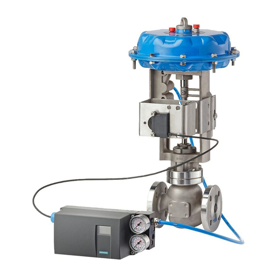
SIPART PS2 with mechanical limit switch module
Operating Instructions (Compact), 04/2007, A5E01179056-01
board rail of the rack.
toward the right.
positioner. Tighten the special screw with a torque of 2 Nm.
NOTICE
A pin is pressed into the actuating disc bearing. Set this pin upright before it is touched
by the special screw. In order that the pins slot into the special screw, you must turn the
actuating disc bearing and the special screw simultaneously.
insulating cover one on side under the mother board surface against the wall of the
container. The recesses in the insulating cover must slot into the corresponding webs on
the container wall.
container walls.
Connect the motherboard and the option modules with the ribbon cables included with
the delivery. Connect the motherboard and the potentiometer with the potentiometer
cable.
module cover.
version of the module cover. Stick the selected plates to the installed module cover as on
the standard version.
3.3 Installing the mechanical limit switch module
Installing
13

