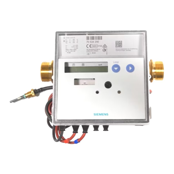
Siemens WZU-485E-MOD Manuale di istruzioni per l'uso - Pagina 2
Sfoglia online o scarica il pdf Manuale di istruzioni per l'uso per Apparecchiature industriali Siemens WZU-485E-MOD. Siemens WZU-485E-MOD 10. Modbus module

Service loop „LOOP 4"
...
6.
Parameterization
6.1
Modbus addressing
The communication module can be addressed in the range 1 –
247. The Modbus address corresponds to the meter's M-Bus
primary address for module slot 1 (AP1). Please set the ad-
dress directly at the meter prior to any further parameterization.
6.2
Setting the primary M-Bus address on the me-
ter display
Call up parameterization mode
Proceed as follows to call up the parameterization operation:
Hold the service button for about 3 s, until
displayed.
Press button 1 to switch the display until
displayed.
Press button 2 to switch the display until
displayed.
Entering the primary M-Bus address
Proceed as follows to enter the primary M-Bus address:
Press button 1 to switch the display until
(primary address for module slot 1) is displayed.
Press button 2 to activate the parameter to be changed.
Press button 2 to change the flashing value.
Press button 1 to enter the set value.
The next point to the right flashes. Repeat the steps above for
all points.
Enter an address in the range from 1 – 247.
The LCD shows a star symbol briefly to confirm.
If the inputs are incorrect, parameterization can be repeated.
Completing address parameterization
Proceed as follows to leave the parameterization operation:
Press button 1 until
Press button 2.
Note: The primary M-Bus address can also be set with
the Service Software UltraAssist.
WZU-485E-MOD
Head of the loop
...
Type "MI / G4" in slot "module 1"
M-Bus Primary address for slot "module 1"
is displayed.
6.3
Parameter setting via USB interface
Requirements:
Micro-USB to USB cable
Computer with Windows OS
Software "WZU-485 Configuration Tool"; can be down-
loaded from www.landisgyr.eu
Attention: The module's power supply must be
switched off before the module is connected to a PC
via USB cable.
Note: The micro-USB interface is used for setting
communication protocol and communication speed
only.
In case the default parameters are suitable for the Modbus
system, no parameterisation is needed.
In other cases, proceed as follows:
Disconnect the screw connector.
Connect the module to a PC via micro-USB to USB cable
Start the software "WZU-485 Configuration Tool".
is
[3]
is
Press the "Read" button [1].
is
The software reads and displays the current parameter settings
of the module.
Make the necessary settings
Press the "Write" button [2].
After successful parameterisation, "Status OK" is displayed
[3].
Close the software.
Disconnect the USB cable from the module.
Insert the screw connector.
Close the meter's cover and affix the seals.
Note: For battery-powered meters: Operating the
communication module with a read-out interval of less
than 10 minutes requires a D-cell battery for 6 years.
Subject to change without prior notice
[1]
[2]
2
