Siemens VGG10.654U Istruzioni tecniche - Pagina 3
Sfoglia online o scarica il pdf Istruzioni tecniche per Unità di controllo Siemens VGG10.654U. Siemens VGG10.654U 9. Gas valves for use with skpxx.xxxux electro-hydraulic actuators
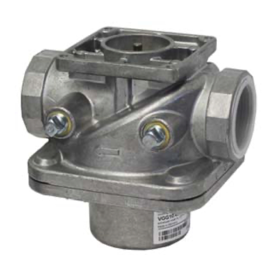
VGG Series Valves
Ordering
Gas valves and actuators are ordered separately. For additional SKPxx.xxxUx actuator
information, see the following technical instructions:
information
SKP15.xxxUx
SKP25.xxxUx
SKP55.xxxUx
SKP75.xxxUx
Product number
Size
NPT
VGG10.154U
½"
VGG10.204U
¾"
VGG10.254U
1"
VGG10.404U
1 ½"
VGG10.504U
2"
VGG10.654U
2 ½"
VGG10.804U
3"
* VGG10.xxxU valves, ½-through 1 ½-inch have reduced flow when used with AGA66 (NEMA 4 kit).
Capacities shown are with/without NEMA 4 kit
Accessories
Part Number
AGA61
AGA66
Siemens AG Building Technologies Division
155-751P25
155-752P25
155-753P25
155-754P25
NOTE:
The SKPxx.xxxUx actuators have an operating temperature range of 14 °F to
140 °F (-10 °C to 60 °C)!
Table 2. Product numbers
Maximum
Close-off
operating
pressure
pressure
psi
psi
20
75
20
75
20
75
20
75
20
75
10
25
10
25
Manual adjusting throttle attachment AGA61 permits VGG10.xxxU series valves to be used as
adjustable limiting orifice valves. Once adjusted, the AGA61 has a provision to be sealed from
tampering.
Sealing gasket to provide NEMA 3, NEMA 3R, and NEMA 4 protection.
- Gasket kit to mount between actuator SKPxx.xxxUx and valve VGG10.xxxU
- Degree of protection increased from IP54 to IP65
- Refer to Mounting Instruction M7643.2 (74 319 0421 0)
Capacity CFH
Number of test
Natural gas at
points, 1/4" NPT
P = 1" W.C.
Inlet
327 / 242*
2
614 / 442*
2
914 / 686*
2
2,047 / 1,643*
2
3,511
2
5,085
1
6,158
1
Description
Technical Instructions
Document Number CC1N7636us
February 09, 2016
Valve body
material
Outlet
2
Aluminum
2
Aluminum
2
Aluminum
2
Aluminum
2
Aluminum
1
Cast iron
1
Cast iron
Page 3