Siemens VN2001-A1 Manuale di istruzioni per l'installazione - Pagina 5
Sfoglia online o scarica il pdf Manuale di istruzioni per l'installazione per Unità di controllo Siemens VN2001-A1. Siemens VN2001-A1 8. Ethernet module 10/100 basetx
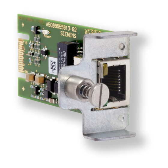
FASTENING PIN
FN2012-A1 ETHERNET
SWITCH (MODULAR)
Figure 6
Mounting the VN2001-A1 Ethernet Module in the FN2012-A1 Ethernet Switch
3. Insert the VN2001-A1 Ethernet Module (10/100 BaseTx) through the knockout opening and
carefully press it into the multi-pin connector mounted on the circuit card inside the switch body.
The multi-pin connector is located approximately 2
4. Screw the fastening pin on the VN2001-A1 module into the mating hole in the side of the
FN2012-A1 Ethernet Switch (modular).
5. Replace the cover on the FN2012-A1 Ethernet Switch (modular).
WIRING
There are no wiring operations for installing the VN2001-A1 onto the VCC2001-A1 Voice CPU card or
into an FN2012-A1 Ethernet Switch (modular).
When using the VN2001-A1 Ethernet Module (10/100 BaseTx) to connect FV2025/2050 Panels, consult
the site-specific shop drawings for instructions on cabling FV2025/2050 Panels together to establish
Ethernet rings. A single multi-conductor cable is used to connect from one module to the next in the ring.
Ethernet cable specifications are provided in Siemens Industry, Inc., Building Technologies Division,
document number A6V10380472 Installation Instructions for the Model VCA2002-A1 Card Cage, Table
2 Cable Specifications.
A6V10370415_en--_a
KNOCKOUT FOR
ETHERNET MODULES
MULTI-PIN
CONNECTORS
5
VN2001-A1 ETHERNET
MODULE (10/100 BASE Tx)
1
/
inches inside the opening.
2
HOLE FOR FASTENING PIN