Siemens 3TM Manuale di istruzioni per l'uso - Pagina 15
Sfoglia online o scarica il pdf Manuale di istruzioni per l'uso per Interruttore Siemens 3TM. Siemens 3TM 48. 1-pole vacuum contactor 4.15 kv - 6.9 kv
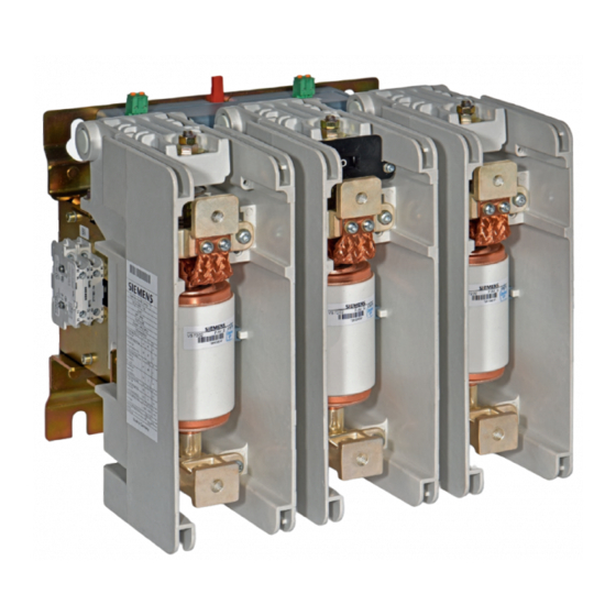
Installation position
High-voltage section
Solenoid actuator
Electronic controller
Supply voltage terminals
9229 0098 176 0-
2019-01-09
Installation position
Observe the distances as per IEC 60071 insulation coordination or comply with the
required leeway distances according to the national operational requirements.
-
Front side: High-voltage section with protection class IP00.
-
Rear side: Low-voltage section with protection class IP20.
The vacuum contactor 3TM can be installed in four positions.
1)
Wall mounting, vertical
2)
Supine position, horizontal
3)
Wall mounting, vertical, rotated 180°
4)
Suspended, with reduced parameters (after consultation with manufacturer)
*)
Observe distance to high-voltage and grounded components!
Fig. 5
Mounting position
The high-voltage section consists of an autonomous pole shell, which can receive
the correspondingly dimensioned vacuum interrupter.
The vacuum interrupter is actuated by a common solenoid actuator. This solenoid
actuator has a very low holding capacity in continuous operation.
The solenoid actuator and the shunt release of the vacuum contactor 3TM can be
actuated with AC or DC.
Vacuum contactors 3TM work according to a defined closing and opening time,
which can be configured and extended by an additional closing and opening delay.
Both delay values are independent of each other and are added to the closing and
opening times.
The electronic controller controls the supply of energy to the solenoid actuator on
closing. The closing current is controlled to a specified level. The current is switched
to the holding current after a specified time. The holding current reduces the vacuum
contactor's energy supply during operation.
The voltage supply of the magnetic unlatching is not affected. The customer is to
deal with the signal control. The maximum signal duration is to be observed, since
the shunt release solenoid only has a limited continuous current strength of 500 ms.
The inrush current (peak) is dependent on the control voltage.
The electronic controller has terminals for the following:
•
supply voltage A1/A2
as well as independent thereof
•
the release voltage for the magnetic unlatching E1/E2 (optional).
Description
15