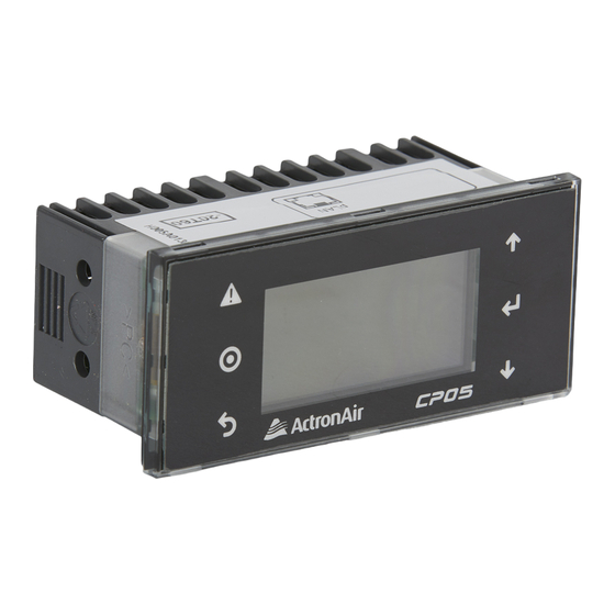
ActronAir CP05 Manuale di installazione - Pagina 10
Sfoglia online o scarica il pdf Manuale di installazione per Unità di controllo ActronAir CP05. ActronAir CP05 16. Control interface

CP05 & CP10 CONTROL INTERFACE INSTALLATION GUIDE
1.2 uPC Control Connection Lay-out (For uPC Controller only)
Please refer to Wiring Diagram provided with your unit for wiring details specific to your requirements.
The Dual Control Connection Lay-out below is provided as a guide only.
6 Core Flat 7/0.12 (AWG28) Telephone Cable
6 Core (3 Pair) Twisted Pair 7/0.20 (AWG24)
Shielded Data Cable 200 Max. Length - Field Scope
10
Prg
Esc
50m Max. Length - Field Scope
(Installer to Provide)
-- or --
(Installer to Provide)
(To be Purchased Separately)
* CP05 or CP10 may be used as Secondary Control Interface.
Refer Control Interface mounting procedure on pages 6-8.
CP10 Control Interface # 1
9:30
Unit: On
Auto
Master Control
23.7
o
C
Return Temp:
16.5
o
C
Supply Temp:
Comp
Rev Vlv
(Supplied & Fitted as Standard)
Control Interface # 2
Remote Mimic Control
CP10 or CP05
uPC Controller
(Supplied & Fitted as Standard)
Electrical Panel
9:30
Unit: On
Auto
23.7
o
C
Return Temp:
Prg
16.5
o
C
Supply Temp:
Comp
Rev Vlv
Esc
CP05 - CP10 Control Interface Insert
Doc. No.0525-035 Ver. 6 220307
