Cisco 6000 series Manuale di installazione dell'hardware - Pagina 18
Sfoglia online o scarica il pdf Manuale di installazione dell'hardware per Router di rete Cisco 6000 series. Cisco 6000 series 30. Network convergence system

Chassis Components
Chassis Components
Table 2-1
considered field replaceable units (FRUs), but where additional detail is useful, identifies
sub-assemblies that are not field replaceable.
Table 2-1
Component
Chassis midplane
Route Processor (RPs)
Card
Fabric Cards (FCs)
Line Cards (LCs)
Fan Trays
Air Filter
Power Trays
Cable management
brackets
Cable troughs
Cisco Network Convergence System 6000 Series Routers Hardware Installation Guide
2-4
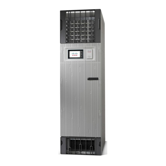
lists the main components of the Cisco NCS 6008 chassis. It identifies the components that are
Main Components of the Cisco NCS 6008 Chassis
Description
Distributes power and provides management, control, and data
interconnections for other components in the system. Each LC is
connected through the midplane to the FCs. The midplane is not field
replaceable by the user.
Two RP cards (RP0/RP1) are inserted into the rear of the chassis. These
cards provide the intelligence of the system by functioning as the system
controller and providing route processing and chassis management. The
RP cards also monitor system alarms and control the system fans. The
LEDs on the front panel indicate active alarm conditions.
Six FCs are inserted into the rear of the chassis. The FCs provide the
switch fabric for the routing system and performs the cross-connect
function of the routing system, connecting every LC to each other. The
switch fabric receives ingress user data from one LC slot and performs the
switching necessary to route the data to the appropriate egress LC slot.
As many as eight LCs can be inserted into the front of the chassis. These
cards provide the physical interfaces and optical connections for the user
data.
Two redundant fan trays are inserted into the front of the chassis. Each fan
tray contains six axial fans. The fans pull cooling air through the chassis
from the front to rear.
A removable air filter is located at the bottom of the chassis, below the
card cage, and inside the front air intake.
Six power trays provide redundant power to the chassis. Both AC and DC
power trays are available. A power tray is a field serviceable unit (FSU).
An AC power tray holds up to three AC power modules (PMs).
•
A DC power tray holds up to four DC PMs.
•
A mixture of AC and DC power is not supported in the chassis.
•
Note
Four horizontal cable management brackets are located on the front-side
and rear-side of the chassis.
The front of the chassis has one bracket above the LC cage and another
•
one below.
The rear of the chassis has one bracket above the card cage and
•
another one below.
Four vertical cable troughs for cable management (two on the front-side
and two on the rear-side of the chassis).
You must power off the chassis before replacing a power tray.
Chapter 2
Chassis Overview
OL-29234-02
