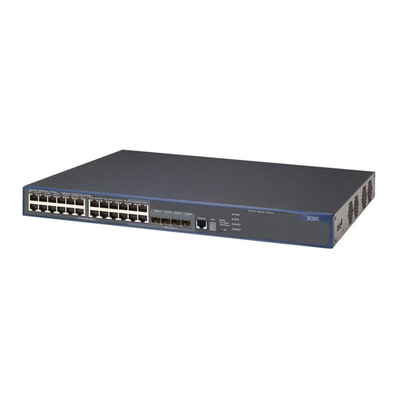
3Com Switch 4800G PWR 24-Port Manuale d'uso - Pagina 2
Sfoglia online o scarica il pdf Manuale d'uso per Interruttore 3Com Switch 4800G PWR 24-Port. 3Com Switch 4800G PWR 24-Port 9. 4800g gigabit series switch
Anche per 3Com Switch 4800G PWR 24-Port: Manuale del prodotto (13 pagine), Scheda tecnica (8 pagine), Scheda tecnica (8 pagine)

H
OW TO
1x
13x
8
Numbered elements in this diagram refer to numbered sections in the
text. These numbers, in bold, are used as references.
Front Panel
1 12 or 24 RJ45 10Base-T Ports
WARNING: RJ-45 Ports. These are shielded RJ-45 data sockets.
They cannot be used as standard traditional telephone sockets,
or to connect the unit to a traditional PBX or public telephone
network. Only connect RJ-45 data connectors, network tele-
phony systems, or network telephones to these sockets.
Either shielded or unshielded data cables with shielded or
unshielded jacks can be connected to these data sockets.
AVERTISSEMENT: Points d'accès RJ-45. Ceux-ci sont protégés
par des prises de données. Ils ne peuvent pas être utilisés comme
prises de téléphone conventionnelles standard, ni pour la con-
nection de l'unité à un réseau téléphonique central privé ou pub-
lic. Raccorder seulement connecteurs de données RJ-45,
systèmes de réseaux de téléphonie ou téléphones de réseaux à
ces prises.
Il est possible de raccorder des câbles protégés ou non protégés
avec des jacks protégés ou non protégés à ces prises de don-
nées.
WARNHINWEIS: RJ-45-Porte. Diese Porte sind geschützte Dat-
ensteckdosen. Sie dürfen weder wie normale traditionelle Tele-
fonsteckdosen noch für die Verbindung der Einheit mit einem
traditionellem privatem oder öffentlichem Telefonnetzwerk
gebraucht werden. Nur RJ-45-Datenanscluße, Telefonnetzsysteme
or Netztelefone an diese Steckdosen anschließen.
Entweder geschützte oder ungeschützte Buchsen dürfen an diese
Datensteckdosen angeschlossen werden.
Either shielded or unshielded data cables with shielded or unshielded jacks
can be connected to these data sockets.
2 MDI Switch
Ports 1 to 11 (12-port hub) and 1 to 23 (24-port hub) are fixed as MDIX
ports so that they can be connected directly to DTE (workstations or other
equipment) which have MDI ports using normal 'straight through' TP
cables.
Port 12 (12-port hub) and 24 (24-port hub) are switch selectable using the
MDI Switch. The ports can be MDIX ports (to connect directly to DTE like
the other ports), or MDI ports (to connect to other repeaters using a
normal 'straight through' TP cable).
Out
In this position you can connect port 12 or 24 to a
workstation or any other DTE using a normal 'straight
through' TP cable.
MDIX
In
In this position you can connect port 12 or 24 to any
MDIX port on another 10BASE-T repeater using a normal
MDI
'straight through' TP cable.
U
B
SE THE
1
6x
7x
18x
19x
9
10
H
ASELINE
UB
2
3
Status
12x
green =
link OK
flashing green =
partition
off =
no link
MDI
1
2
3
4
5
6
7
MDIX
13
14
15
16
17
18
19
24
Unit 1
Unit 2
To connect two Baseline Hubs, connect port 12 or 24 on unit 1 to any
port on unit 2. Ensure that the MDI switch on unit 1 is IN (MDI) and that
if port 12 or 24 is used on unit 2, the MDI switch is OUT (MDIX).
3 TP Status LEDs
The TP Status LEDs show the partition state of a port and whether or not
the Link Pulse signal is present on the segment connected to a port:
Green
Flashing
green
Off
If these checks do not identify the cause of a problem, it may be that the
Baseline Hub or the device connected to the port is faulty. Contact your
supplier for further advice.
2
4
5
6
7
Baseline Hub
8
9
10
11
12 TCVR
Traffic
Collision
Power
20
21
22
23
24
3C16641A SuperStack 3
Switch set to MDIX (out)
if port 24 used
The Link Pulse signal is being received and the segment attached
to the port is functional.
The port is partitioned from the network.
Check the connections and the cable for any breaks in the
segment.
Make sure the transceiver attached to the DTE is correctly
connected and powered up.
Check for illegal 802.3 configurations, in particular, loops.
If the cause of the partition is found and corrected, the segment is
reconnected automatically, after the first valid packet is
transmitted to, or received from the segment.
The Link Pulse signal is not being received.
Check that the attached DTE is switched on.
Check that the attached transceiver is not faulty.
If it is port 12 or 24 or an inter-repeater link, check the setting
of the MDI switch.
Carry out the checks recommended for when a Status LED is
flashing green.
Check for no more than 4 repeater stacks in series, and that
cable lengths do not exceed the maximum specified in the
standard for that medium.
®
11
Set switch to
MDI (in)
