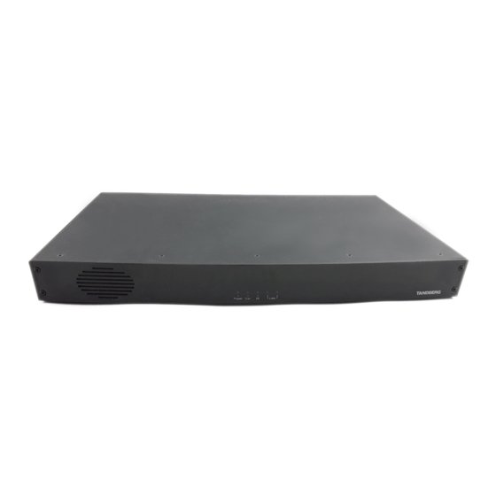
Cisco MXP Series Il manuale dell'interfaccia fisica - Pagina 22
Sfoglia online o scarica il pdf Il manuale dell'interfaccia fisica per Sistema di conferenze Cisco MXP Series. Cisco MXP Series 28.

MXP Series Codecs
Contents
Camera Socket
TIP!
Wherever applicable, the use of Category
5 cabling or better is strongly recommended!
For HD camera applications, however,
Category 7.5 is required.
S-video Mini-DIN pin-out
Split cable for
External view of socket
non-Cisco
cameras
4
3
2
1
Pin 1: Ground (Luminance)
Pin 2: Ground (Chrominance)
Camera side
Pin 3: Luminance (Y)
Pin 4: Chrominance (C)
9-pin D-sub pin-out
External view of socket
1
5
SIGNAL
NAME
+12V DC
GND
9
6
+12V DC
TXD
RXD
RJ-45 Connector
GND
pin-out
GND
+12V DC
1
8
Y-GND
TOP
C_GND
Y
C
FRONT
NC
1
8
D14790.01 MXP Series Codec Physical Interface Guide, May 2011.
© 2011 Cisco Systems, Inc. All rights reserved.
Introduction
Codec side
TANDBERG 3000 WAVE II
Camera cable pin-out
RJ-45
S-VIDEO
DSUB
8
—
4
7
—
5
3
—
4
4
—
3
5
—
2
6
—
5
2
—
5
1
—
4
—
1
8
—
2
1
—
3
9
—
4
6
—
—
7
Codec 6000 MXP
Camera Connect the camera here. Use
a Cisco 3000 WAVE II Camera cable or
similar.
To connect a non-Cisco camera use
the split cable supplied. This cable
has a female D-SUB and an S-video
connector in one end and a male
D-SUB connector in the other end.
TANDBERG HD 3000
Camera cable pin-out
SIGNAL
RJ-45
DSUB
NAME
+12V DC
1
Twisted pair
GND
2
Rx
3
Twisted pair
TX
6
LVDS+
4
Twisted pair
LVDS–
5
GND
7
Twisted pair
+12V DC
8
Cable is Category 7.5/ Class F AWG24.
CAUTION!
Extreme care should be taken if
you choose to make your own version of this
cable!
22
Physical interface guide
Codec 3000 MXP
Codec 3000 MXP
Non-TANDBERG
Camera cable pin-out
SIGNAL
DSUB
S-VIDEO
NAME
Camera
4
+12V DC
1
—
1
GND
2
—
2
+12V DC
3
—
3
TXD
4
—
6
RXD
5
—
9
GND
6
—
5
GND
7
—
4
+12V DC
8
—
Y-GND
—
1
C_GND
—
2
Y
—
3
C
—
4
NC
—
—
Contact us
DSUB
Codec
4
5
4
3
2
5
5
4
8
1
9
6
7
www.cisco.com
