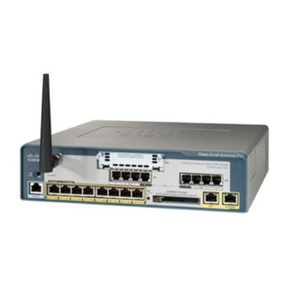
Cisco UC500 series Manuale di configurazione - Pagina 6
Sfoglia online o scarica il pdf Manuale di configurazione per Sistema di conferenze Cisco UC500 series. Cisco UC500 series 50. Sip trunking unified communications 500 series

Figure 1 depicts the topology that was used in this guide
Figure 2.1 Topology
Managed Access Router
UC500
Interface Vlan1 192.168.10.1
Interface Vlan100 10.1.1.1
IP Phones
In this topology, UC500 is placed inline between the managed access router and
CPE devices including IP phones and personal computers. UC500 becomes the
default gateway, TFTP, and DHCP server for the phones and PCs. Requirements
for this configuration include:
• A layer 2 Ethernet switch or cross over cable between the Managed
Access Router and UC500
• Cisco UC500 appliance
• Cisco IP Phones, up to 48 with CE520 expansion switches.
• Miscellaneous analog phones or other devices such as fax machines
© 2008 Cisco Systems, Inc. All rights reserved.
SP Network
Crossover Ethernet
PCs
Fa0/0
Fa0/1/0 thru 0/1/7
VLAN 100 10.1.1.0 /24
VLAN 1 192.168.10.0 /24
