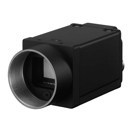
Sony XCG-CG160C Manuale - Pagina 5
Sfoglia online o scarica il pdf Manuale per Fotocamera digitale Sony XCG-CG160C. Sony XCG-CG160C 9. Digital video camera
Anche per Sony XCG-CG160C: Manuale (9 pagine)

Location and Function of Parts and Controls
➀
Lens mount (C-mount)
Attach any C-mount lens or other optical equipment.
Note
Use a C-mount lens with a protrusion (a) extending from the lens
mount face (b) of 10 mm (13/32 inch) or less.
➁
Guide screw holes (Top)
➂
Guide screw holes/Tripod screw holes (bottom)
When using a tripod, use these four screw holes to attach
a VCT-333I tripod adaptor.
➃
Reference screw holes (bottom)
These precision screw holes are for locking the camera
module. Locking the camera module into these holes
secures the optical axis alignment.
Rear Panel/Pin Assignments
➄
➄
DC IN (DC power input) connector (6-pin)
You can connect a camera cable to input the +12 V DC power
supply. The pin configuration of this connector is as follows.
(Refer to Fig. 6 above for the pin assignment of the
Pin No.
Signal
DC input
1
(10.5 V to 15 V)
2
GPI1 (ISO +)
3
GPI2/GPO2
* only XCG-CG160/CG160C/CG40
RJ45 connector
➅
You can connect a LAN cable to this connector to control the
camera module from a host device to output image to a host
device. By using a PoE-compatible LAN cable and camera
module interface board or hub, you can supply power using the
LAN cable.
Note
For safety, do not connect the connector for peripheral device
wiring that might have excessive voltage to this port.
Reset switch
➆
The camera can be reset to the factory setting by pressing the
reset switch for more than 3 seconds while the power is turned
on.
➇
Status LED (Green)
This button is lit when power is being supplied to the camera.
Various settings linked with GPO are available, such as to light
up when interlocking with the trigger signal.
This button blinks when the network is disconnected, or while 1P
is being acquired.
➀
➁
a
b
➂
➃
➅
➆
➇
connector.)
Pin No.
Signal
GPI3/GPO3
4
(GPO3 (ISO +)*)
5
GPI1 (ISO –)
6
GND
Connecting the Cables
1
2
Connect the camera cable to the DC IN connector and connect the
LAN cable to the RJ45 connector respectively. If you use a camera
module interface board or a hub that supports PoE, you can
operate the camera even if you do not connect the camera cable
to the DC IN connector. When you connect the LAN cable with
fastening screws, turn the two screws on the connector to secure
the cable tightly.
Connect the other end of the camera cable to the DC-700/700CE
and the other end of the LAN cable to the camera module interface
board or a hub.
➀
RJ45 connector
➁
DC IN connector
➃
➄
Fastening screws
Camera cable
Note
Do not supply power to the camera cable and LAN cable
at the same time.
Controlling the Camera From the Host Device
Control functions
Operating mode
Free run
Trigger edge
Shutter speed
detection
Trigger pulse
width detection
Gain
Partial Scan
(the number of settable lines are 16 or more)
LUT (Look Up Table)
External trigger input
Monochrome model: Mono 8 / 10 / 12 bit
Video output switch
Color model: Raw 8 /10 /12 bit, RGB24 bit,
Defect correction
Shading correction*
Image flip
Area gain
* except XCG-CG40
XCG-CG510/CG510C/CG240/CG240C/CG160/CG160C/CG40
3
4
5
➂
LAN cable
Description
Free run/Trigger
1/40,000 s to 60 s (CG240)
1/100,000 s to 60 s (CG510/CG160/CG40)
1/40,000 s to 60 s (CG240)
1/100,000 s to 60 s (CG510/CG160/CG40)
Setting by trigger pulse width
0 dB to 18 dB
Variable, 4-line increments
OFF/ON (Mode: 5 types)
DC IN connector
YUV24 bit, YUV16 bit
OFF/ON
OFF/ON
OFF/ON
OFF/ON
