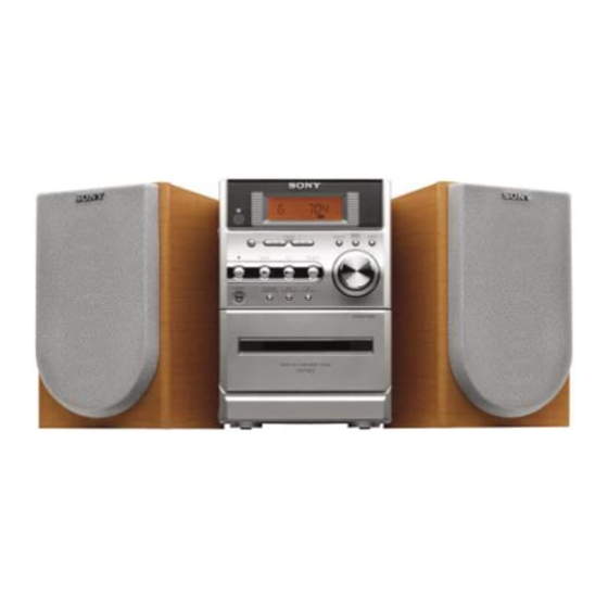
Sony SS-CNE3 Manuale di servizio - Pagina 34
Sfoglia online o scarica il pdf Manuale di servizio per Impianto stereo Sony SS-CNE3. Sony SS-CNE3 48.

HCD-NE3
• IC Pin Function Description
CONTROL BOARD IC801 LC877456C-53K5-E (SYSTEM CONTROLLER)
Pin No.
Pin Name
PWR ON
1
CD ON
2
3
CD XTXCN
4
CD OPEN
5
CD XRST
6
CD DATA
7
CD SENS
8
CD CLK
9
CD XLT
10
NC
11
RESET
12
XT1
13
XT2
14
VSS1
15
CF1
16
CF2
17
VDD1
I POWER
18
MONITOR
19, 20
NC
21
AREA
22
VOL ENCODER
23
I POWER DOWN
24
TA-SW
25, 26
KEY1, KEY0
27
CD SCOR
28
F DATA
29
RMC
30
TU DI
31
NC
32
TU DO
33
TU MUTE
34
TU CLK
35
TU CE
36
TU TUNED
37
TU STEREO
38
NC
ST/BY
39
MD LED
40
30
I/O
O
Power relay drive signal output terminal
O
Power on/off control signal output for the CD mechanism section
Oscillation circuit control signal output to the CD DSP
O
"H": auto oscillation, "L": oscillation off
I
CD lid open/close detection switch input terminal
O
Reset signal output to the CD DSP
O
Serial data output to the CD DSP
I
Internal status (SENSE) signal input from the CD DSP
O
Serial data transfer clock signal output to the CD DSP
O
Serial data latch pulse output to the CD DSP
—
Not used
Reset signal input from the reset switch "L": reset For several hundreds msec. after the power
I
supply rises, "L" is input, then it changes to "H"
I
Sub system clock input terminal (32.768 kHz)
O
Sub system clock output terminal (32.768 kHz)
—
Ground terminal
I
Main system clock input terminal (10 MHz)
O
Main system clock output terminal (10 MHz)
—
Power supply terminal (+3.2V)
I
Power monitor input terminal
—
Not used
I
Model destination setting terminal
I
Dial pulse input of the rotary encoder (for VOLUME control)
I
Power down detection signal input terminal "L": power down, normally : "H"
I
Cassette in/out detect switch signal input from the tape mechanism deck "L": cassette in
I
Front panel key input terminal (A/D input)
I
Subcode sync (S0+S1) detection signal input from the CD DSP
O
Serial data output to the electrical volume
I
Remote control signal input from the remote control receiver
I
Serial data input from the FM/AM tuner unit
—
Not used
O
Serial data output to the FM/AM tuner unit
O
Tuner muting on/off control signal output to the FM/AM tuner unit
O
serial data transfer clock signal output to the FM/AM tuner unit
O
Chip enable signal output to the FM/AM tuner unit
I
Tuning detection signal input from the FM/AM tuner unit
I
FM stereo detection signal input from the FM/AM tuner unit
—
Not used
O
LED drive signal output terminal
O
LED drive signal output terminal
Description
"H": on
