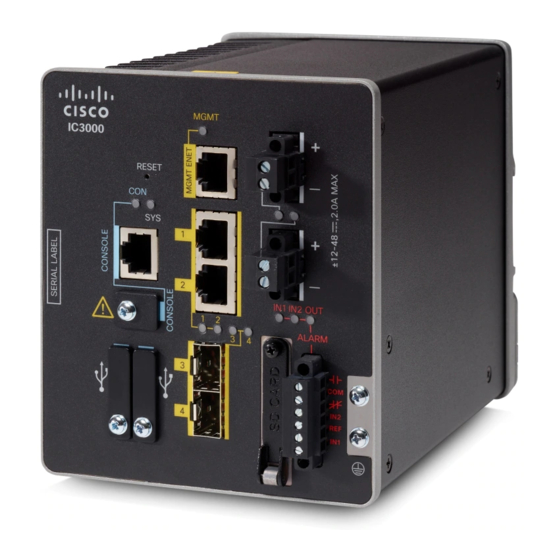
Cisco IC3000 Manuale di installazione dell'hardware - Pagina 29
Sfoglia online o scarica il pdf Manuale di installazione dell'hardware per Porta d'ingresso Cisco IC3000. Cisco IC3000 37. Industrial compute gateway
Anche per Cisco IC3000: Documentazione del prodotto (12 pagine)

Connecting the Cisco IC3000
Figure 10: Stripping the Power Connection Wire
Step 5
Remove the two captive screws that attach the power connector to the device, and remove the power connector. Remove
both connectors if you are connecting to two power sources.
Step 6
On the power connector, insert the exposed part of the positive wire into the connection labeled "+" and the exposed part
of the return wire into the connection labeled "–". The "+" is the Power source positive connection, and the "-" is the
Power source return connection. See
Figure 11: Inserting Wires into the Power Connector
Note
Ensure that you cannot see any wire lead. Only wire with insulation should extend from the connector.
Step 7
Use a ratcheting torque flathead screwdriver to torque the power connector captive screws (above the installed wire leads)
to 2 in-lb (0.23 N-m). See #1 in
Do not over-torque the power connector's captive screws. The torque should not exceed 2 inch-lbs (0.23 N-m).
Note
Figure 11: Inserting Wires into the Power Connector, on page
Figure 12: Torquing the Power Connector Captive Screws, on page
Cisco IC3000 Industrial Compute Gateway Hardware Installation Guide
Connecting to DC Power
27.
28.
27
