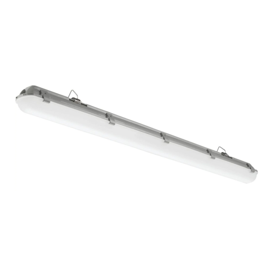
Acuity Brands Lithonia Lighting XVML Manuale di istruzioni per l'installazione - Pagina 4
Sfoglia online o scarica il pdf Manuale di istruzioni per l'installazione per Apparecchio di illuminazione Acuity Brands Lithonia Lighting XVML. Acuity Brands Lithonia Lighting XVML 8.

The XVML luminaires have been designed and tested in accordance with applicable UL standards and are suit-
Hardware requirements will depend on the mounting method. Determine fi xture location, orientation and
PREPARING THE FIXTURE
FOR INSTALLATION
Note: Turn off power at circuit breaker box!
1. Unlatch Diffuser (2) and open. Note: two latches on one side
remain captive to Diffuser.
2. Open Wireway cover (3) by rotating Cover Latches (7). Remove
fi xture components and parts pack(s). Check that all parts are
included.- See Fig.1 on page 3
Note: Fixture is supplied with a Liquid-tight fi tting installed for
Conduit- XVML 3500LM (3/8"), XVML 5000LM (1/2")
Fixture can be installed with Through-Wiring.
If requires Through-Wiring installation- the knockout on opposite
end of fi xture must be removed and a 7/8" dia. hole must be
drilled through plastic housing in the designated location.
Max. Linking: 15 units or 6A Max.
Semi-Flush Installation
Follow steps 3 & 4.
If mounting to a metal surface- additional hardware will need to be
purchased.
3. Mark location for mounting holes. Mounting brackets (6) can be
installed 29-5/8"- 33-1/4" apart on mounting surface (center of
bracket to center of bracket). For each bracket, drill 3/32" pilot
holes.
If drill encounters ceiling joist, Install bracket with wood
screws (9) (included). Tighten screws to secure bracket to
mounting surface. See Fig. 2. Repeat for other mounting
bracket.
If drill does not encounter ceiling joist, drill ½" holes
in mounting surface. Install bracket (6) with toggle nut and 3"
screws (10) (included). Tighten screws to secure bracket.
See Fig 3. Repeat for other mounting bracket.
4. Lift fi xture housing (1) to mounting brackets (6) and snap in
place. See Fig. 4. Confi rm fi xture is securly mounted.
Suspended Installation
Follow steps 5 thru 8.
(Support arm for chain mounting is included- chain and related
hardware is not included and must be purchased separately.)
5. Mark location for two mounting holes on mounting surface and
secure chain to mounting surface.
6. Install wire support arms to mounting brackets (6) by snapping
into oval slots. See Fig. 4
7. Snap mounting bracket (6) onto back of fi xture housing. See
Fig. 4
able for use in wet locations.
THIS FIXTURE HAS OPTIONAL MOUNTING METHODS
mounting method before proceeding.
CHOOSE YOUR PREFERRED OPTION:
SEMI-FLUSH MOUNTING
SUSPENDED MOUNTING
Wire Support Arm
Page 4
Figure 2
Figure 3
Mounting Bracket
Figure 4
