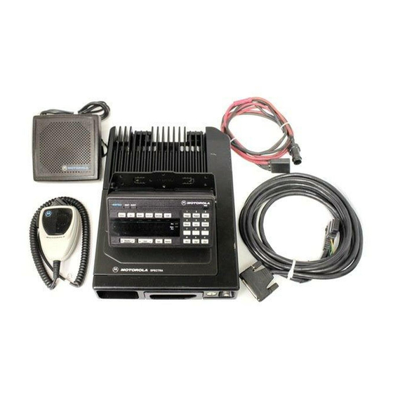
Motorola ASTRO Digital Spectra Manuale di installazione - Pagina 20
Sfoglia online o scarica il pdf Manuale di installazione per Radio bidirezionale Motorola ASTRO Digital Spectra. Motorola ASTRO Digital Spectra 32. Fm two-way mobile radios
Anche per Motorola ASTRO Digital Spectra: Elenco delle parti (13 pagine)

Transmit/Receive
Control Cable
Installation (A4, A5,
A7, and A9 Remote
Control Heads)
14
IMPORTANT
USE A METAL BACKING PLATE
(NOT SUPPLIED) IF MOUNTING
TRUNNION ON A PLASTIC DASHBOARD
DRILL FOUR 5/32"
HOLES IN DASHBOARD
DASHBOARD
TRUNNION
03-00136756
USE FOUR MOUNTING SCREWS
ON ALL INSTALLATIONS
ADJUST THE CONTROL HEAD
TO DESIRED ANGLE AND
SECURE WITH WING SCREWS
VIP CONNECTOR
MICROPHONE
Figure 12 A9 Control Head Installation Exploded View
The radio system includes two separate wires, one orange (66") and one
green (106"). The HLH4952A Fuse Kit contains crimp-on ring tongue lugs
and crimp-on spade lugs. The spade lugs allow connection to hot leads at
the fuse block of the vehicle, and the ring tongue lugs permit attachment
to screw terminals. Determine from Table 1 which radio functions are to be
switched through the vehicle ignition switch.
A typical system allows the receiver to operate with the radio switched on
while the ignition switch is in the off position, but the transmitter will not
operate unless the ignition switch is in the on position. In this case, connect
the orange wire to the accessory terminal of the ignition switch and the
green wire to the ungrounded terminal of the battery or starter solenoid.
!
DO NOT connect either lead to the ungrounded terminal of
the battery at this time.
C a u t i o n
ORANGE AND
TO
GREEN LEADS
RADIO
TO
DESCRIPTION
A9 Control Head Installation
TO
SPEAKER
MAEPF-21373-0
TECHNICAL PUBLICATIONS DEPT.
DWG. NO.
MAEPF-21373
