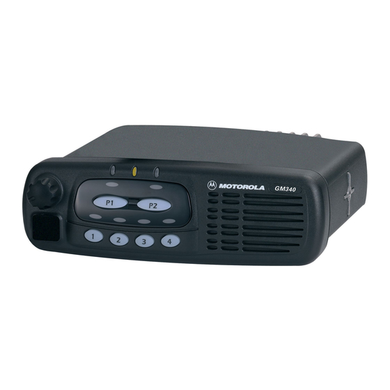
Motorola GM Series Informazioni sul servizio - Pagina 4
Sfoglia online o scarica il pdf Informazioni sul servizio per Radio Motorola GM Series. Motorola GM Series 34. Professional radio
Anche per Motorola GM Series: Manuale di servizio (28 pagine), Manuale di installazione (36 pagine)

iv
Chapter 3
1.0 Troubleshooting Flow Chart for Receiver (Sheet 1 of 2) ..................................... 3-1
1.1 Troubleshooting Flow Chart for Receiver (Sheet 2 of 2) ..................................... 3-2
2.0 Troubleshooting Flow Chart for 25W Transmitter (Sheet 1 of 3) ......................... 3-3
2.1 Troubleshooting Flow Chart for 25W Transmitter (Sheet 2 of 3) ......................... 3-4
2.2 Troubleshooting Flow Chart for 25W Transmitter (Sheet 3 of 3) ......................... 3-3
3.0 Troubleshooting Flow Chart for 45W Transmitter (Sheet 1 of 2) ......................... 3-4
3.1 Troubleshooting Flow Chart for 45W Transmitter (Sheet 2 of 2) ......................... 3-4
4.0 Troubleshooting Flow Chart for Synthesizer........................................................ 3-5
5.0 Troubleshooting Flow Chart for VCO................................................................... 3-6
Chapter 4
VHF PCB/SCHEMATICS/PARTS LISTS
1.0 Allocation of Schematics and Circuit Boards ....................................................... 4-1
1.1 Controller Circuits ................................................................................................ 4-1
2.0 VHF 1-25W PCB 8486172B04 / Schematics....................................................... 4-3
2.1 VHF 1-25W PCB 8486172B04 Parts List ......................................................... 4-10
3.0 VHF 1-25W PCB 8486172B06 / Schematics..................................................... 4-13
3.1 VHF 1-25W PCB 8486172B06 Parts List .......................................................... 4-20
4.0 VHF 1-25W PCB 8486172B07 / Schematics..................................................... 4-23
4.1 VHF 1-25W PCB 8486172B07 Parts List .......................................................... 4-27
5.0 VHF 25-45W PCB 8486140B12 / Schematics................................................... 4-30
5.1 VHF 25-45W PCB 8486140B12 Parts List ........................................................ 4-33
