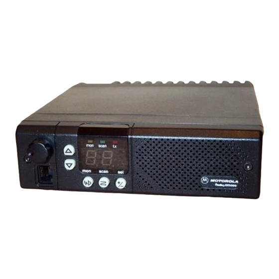
Motorola RADIUS GM300 Manuale di servizio - Pagina 26
Sfoglia online o scarica il pdf Manuale di servizio per Radio Motorola RADIUS GM300. Motorola RADIUS GM300 49. 16-channel, conventional fm radio
Anche per Motorola RADIUS GM300: Manuale di servizio (28 pagine), Manuale di istruzioni per l'uso (18 pagine), Manuale di istruzioni per l'uso (19 pagine), Manuale d'uso (37 pagine), Istruzioni per l'uso (2 pagine)

RF Board
VHF Receiver Front End, 146-174 MHz
The received signal applied to the radioÕs antenna
input connector is Þrst routed through the harmonic
Þlter/antenna switch on the RF Power AmpliÞer
Board, and then applied via coax to J4 on the RF Board.
The insertion loss of the harmonic Þlter/antenna
switch is less than 1 dB.
The signal applied to J4 is routed to a Þxed-tuned 4-
pole Þlter having a 3 dB bandwidth of 57 MHz and a
1 dB bandwidth of 37 MHz centered at 160 MHz. Inser-
tion loss is 1.5 dB typically, and 2 dB at 146 MHz. Atten-
uation for image protection is 32 dB at 236 MHz, with
increasing attenuation at higher frequencies.
The output of the Þlter is matched to the base of RF
ampliÞer Q1, which provides 12 dB of gain and has a
noise Þgure of 3.6 dB. Current source Q2 is used to
maintain the collector current of Q1 constant at 26 mA.
Diode CR2 clamps excessive input signals, protecting
Q1.
The output of Q1 is applied to a 3-pole Þxed-tuned Þl-
ter having a 3 dB bandwidth of 59 MHz and a 1 dB
bandwidth of 48 MHz centered at 160 MHz. Insertion
loss is 1.3 dB. Attenuation for image protection is 35 dB
at 236 MHz, with increasing attenuation at higher fre-
quencies. Additional image protection is provided by
the transmitter harmonic Þlter, which provides at least
20 dB of attenuation at 236 MHz and above.
A pin diode attenuator is located between the 3-pole
Þlter and the Þrst mixer. In the Distance mode, Q5 and
Q6 are turned on, CR5 is forward-biased which
bypasses R12, and no loss is introduced. In the Local
mode, Q5, Q6 and CR5 are off, inserting 10 dB of atten-
uation due to R12. Because the attenuator is located
after the RF ampliÞer, receiver sensitivity is reduced
only by 5 dB, while the overall third order input inter-
cept is raised by 15 dB. Thus, the Local mode signiÞ-
cantly reduces the susceptibility to IM-related
interference.
The Þrst mixer is a passive, double-balanced type con-
sisting of T1, T2 and U1. This mixer provides all of the
necessary rejection of the half-IF spurious response,
since the improvement due to Þlter selectivity is negli-
gible for much of the band. High-side injection at
March, 1997
Theory of Operation
+13 dBm is delivered to the Þrst mixer from the second
RX buffer in the synthesizer circuit.
The mixer output is connected to a diplexer network
which matches its output to the Þrst IF ampliÞer Q51 at
the IF frequency of 45.1 MHz, and terminates it in a
50 ohm resistor, R51, at all other frequencies.
UHF Receiver Front End
The received signal applied to the radioÕs antenna
input connector is Þrst routed through the harmonic
Þlter/antenna switch on the RF Power AmpliÞer
Board, and then applied via coax to J4 on the RF Board.
The insertion loss of the harmonic Þlter/antenna
switch is less than 1 dB.
The signal applied to J4 is routed to a Þxed-tuned 3-
pole shunt resonator Þlter having the following charac-
teristics:
Range
403-433
1 dB BW:
41 MHz
3 dB BW:
77 MHz
Loss:
3 dB
f
:
418 MHz
CENTER
Image Rej:
33 dB
At f
:
343 MHz
IMAGE
Attenuation for image protection increases for frequen-
cies lower than f
IMAGE
The output of the Þlter is matched to the base of RF
ampliÞer Q1. Current source Q2 is used to maintain the
collector current of Q1 constant at 30 mA. Transistors
Q3 and Q4 turn off the DC supply to Q1 and Q2 during
transmit, reducing the dissipation in Q1. Diodes CR2
and CR3 clamp excessive input signals, protecting Q1.
The RF ampliÞer parameters are:
Range
403-433
Gain:
16 dB
N.F.:
1.4 dB
The output of Q1 is applied to a tunable 4 pole shunt
resonator Þlter with these characteristics:
68 No.
438-470
465-495
490-520
45 MHz
40 MHz
40 MHz
65 MHz
60 MHz
55 MHz
1.8 dB
2.2 dB
2.2 dB
455 MHz
480 MHz
510 MHz
30 dB
35 dB
37 dB
380 MHz
405 MHz
430 MHz
.
438-470
465-495
490-520
15 dB
15 dB
15 dB
1.4 dB
1.8 dB
1.8 dB
2-1
