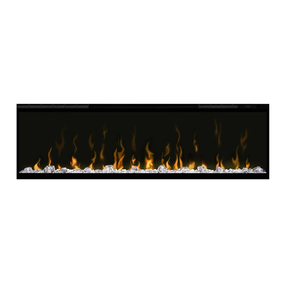
Dimplex 6910000100 Manuale di servizio - Pagina 14
Sfoglia online o scarica il pdf Manuale di servizio per Camino da interno Dimplex 6910000100. Dimplex 6910000100 18.
Anche per Dimplex 6910000100: Manuale di servizio (18 pagine)

2. Remove the screws that secure the holding bracket
and power supply to the unit.
3. Trace the wires to the main control board and discon-
nect.
4. Run the wiring from the new power supply to the main
control board.
5. Reinstall the bracket.
6. Ensure that all wires are replaced in the same manner
as prior to the service.
7. Reassemble in the reverse order as above.
Capacitive Controls and Display
Replacement
WARNING: Disconnect power before attempting any
maintenance or cleaning to reduce the risk of electric
shock or damage to persons.
CAUTION: If unit was operating prior to servicing allow
at least 10 minutes for lights and heating elements to cool
off to avoid accidental burning of skin.
Tools required: Phillips head screwdriver
CAUTION: Follow "Preparation for Service" instructions
before proceeding.
1. In the upper right hand corner of the unit, above the
main control board, locate the controls and display
assembly and remove the 2 securing screws. (Figure 6)
1. Gently remove the assembly from the unit by pulling it
forward. (Figure 12)
2. Disconnect the wire from the old assembly and install it
on the new assembly.
3. Reinstall the new board onto the unit.
4. Ensure that all wires are replaced in the same manner
as prior to the service.
5. Reassemble in the reverse order as above.
Figure 7
Media Tray screws (4)
14
Media LED Light Strips Replacement
WARNING: Disconnect power before attempting any
maintenance or cleaning to reduce the risk of electric
shock or damage to persons.
CAUTION: If unit was operating prior to servicing allow
at least 10 minutes for lights and heating elements to cool
off to avoid accidental burning of skin.
Tools required: Phillips head screwdriver
CAUTION: Follow "Preparation for Service" instructions
before proceeding.
1. Remove the plastic media tray by removing the 4
screws: 2 on the left and 2 on the right of the tray.
(Figure 7)
2. Lift the plastic media tray out of the unit.
3. Remove the front panel by removing the 6 screws: 3 on
the left and 3 on the right of the tray.
4. Locate the LED assembly that needs to be removed.
5. Disconnect the wiring connections at either end.
6. Remove the assembly by pinching the plastic mounting
tabs with needle nose pliers and lifting off.
7. Install the new assembly onto the unit and secure the
LED strip to the unit.
8. Reattach the wire connections.
9. Ensure that all wires are replaced in the same manner
as prior to the service.
10. Reassemble in the reverse order as above.
Flame LED Strips Replacement
WARNING: Disconnect power before attempting any
maintenance or cleaning to reduce the risk of electric
shock or damage to persons.
CAUTION: If unit was operating prior to servicing allow
at least 10 minutes for lights and heating elements to cool
off to avoid accidental burning of skin.
Tools required: Phillips head screwdriver
CAUTION: Follow "Preparation for Service" instructions
before proceeding.
1. Remove the plastic media tray by removing the 4
screws: 2 on the left and 2 on the right of the tray.
(Figure 7)
2. Lift the plastic media tray out of the unit.
Front
3. Remove the front panel by removing the 6 screws: 3 on
Panel
the left and 3 on the right of the tray.
4. Remove the 17 screws along the top of the flame panel
and gently remove. (Figure 6)
5. Locate the LED strip that needs to be removed.
6. Disconnect the wiring connections at either end.
7. Remove the LED strip by pinching the plastic mounting
tabs with needle nose pliers and lifting off.
Needle nose pliers
Wire cutters
www.dimplex.com
