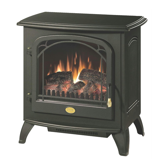
Dimplex DS5804 Manuale di servizio - Pagina 10
Sfoglia online o scarica il pdf Manuale di servizio per Stufa Dimplex DS5804. Dimplex DS5804 13. Electric
Anche per Dimplex DS5804: Manuale pratico per l'utente (11 pagine), Manuale d'uso (14 pagine), Manuale d'uso (16 pagine)

12. Locate and remove the rear heater mounting screws.
13. Locate and disconnect the power cord wiring connec-
tions noting their original locations.
14. With needle nose pliers grasp the power cord strain relief
grommet from inside the heater cover and push while
twisting to remove.
15. Pull the power cord out through the hole in the heater
cover.
16. Install the new power cord through the hole in the heater
cover and connect all of the wiring connections in their
original locations.
17. Install the power cord retaining grommet on the power
cord and insert into the hole in the heater cover.
18. Reassemble in the reverse order as above.
Mod C and Higher
Tools Required: Philips head screwdriver
Flat head screwdriver
Needle-nose pliers
WARNING: If the fireplace was operating prior to servic-
ing, allow at least 10 minutes for light bulbs and heating ele-
ments to cool off to avoid accidental burning of skin.
WARNING: Disconnect power before attempting any
maintenance to reduce the risk of electric shock or damage
to persons.
1. Remove the stove pipe kit (if equipped).
2. With front door closed, gently place stove door side down
on a flat surface.
3. Remove the retaining screws on the REAR stove legs
with a screwdriver and remove the rear legs.
4. Remove the rear cover retaining screw located at the
lower center of the rear cover.
5. Slide the rear cover down 4 to 6 inches and gently pull
the cover up from both the top and bottom bowing it
slightly and remove it from its mounting slot. When the
cover is removed place beside the stove being careful
not to damage any of the wiring.
6. Locate and disconnect the power cord wiring connec-
tions noting their original locations.
7. Remove the heater cover retaining screws located on the
bottom of the stove with a screwdriver.
8. Lower the heater cover off of the bottom of the stove be-
ing careful not to damage any of the wiring.
9. With needle nose pliers grasp the power cord strain relief
grommet from inside the heater cover and push while
twisting to remove.
10. Pull the power cord out through the hole in the heater
cover.
11. Install the new power cord through the hole in the heater
cover and connect all of the wiring connections in their
original locations.
12. Install the power cord retaining grommet on the power
cord and insert into the hole in the heater cover.
13. Reassemble in the reverse order as above.
Heater Assembly Replacement
Mod 0-B
Tools Required: Philips head screwdriver
Flat head screwdriver
WARNING: If the fireplace was operating prior to servic-
ing, allow at least 10 minutes for light bulbs and heating ele-
ments to cool off to avoid accidental burning of skin.
WARNING: Disconnect power before attempting any
maintenance to reduce the risk of electric shock or damage
to persons.
1. Do to the partial disassembly of the stove care must be
taken not to scratch any surfaces or damage any compo-
nents during the repair.
2. Remove the stove pipe kit (if equipped).
3. Open the door by turning the handle ¼ of a turn to the
right or left.
4. Locate the cam locks on the side panels inside the upper
corners of the stove and turn with a large slot screwdriver
so the triangle on the cam lock is pointing up towards the
top of the stove.
5. Close the front door and turn the handle ¼ of a turn to
lock.
6. Gently place the stove, door side down on a flat surface.
7. Remove the retaining screws on the REAR stove legs
with a screwdriver and remove the rear legs.
8. Remove the rear cover retaining screw located at the
lower center of the rear cover.
9. Slide the rear cover down 4 to 6 inches and gently pull
the cover up from both the top and bottom bowing it
slightly and remove it from its mounting slot. When the
cover is removed place it beside the stove being careful
not to damage any of the wiring.
10. Locate the cam locks on the side panels inside the upper
corners of the stove and turn with a large slot screwdriver
so the triangle on the cam lock is pointing up.
11. Grasp the top at both sides and gently pull up to release
the top.
12. Locate and remove the partially reflective glass by pulling
it out of the slots being careful not to bump or drop it.
13. Locate the cam locks on both of the sides of the bottom
panel, turn with a large slot screwdriver so the triangle on
the cam lock is pointing towards the side panels.
14. Gently pull the side panels apart slightly from the rear of
the stove to release the center plate.
15. Remove the plate by pulling up and out from the back
being careful not to damage any of the wiring.
16. Locate and remove all of the heater assembly retaining
screws from the bottom panel. Some if the screws are
located under the reflective sheet.
17. Lift the heater assembly up through the bottom panel and
separate the heater assembly from the mounting plate
and the bottom cover.
18. Disconnect the wiring clips and connections noting their
original locations.
!
NOTE: Use a flat head screwdriver to gently pry be-
10
