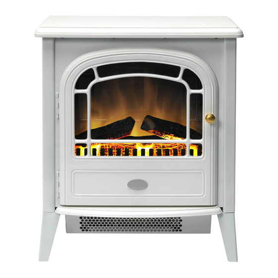
Dimplex RIT20 Istruzioni per l'installazione e il funzionamento - Pagina 2
Sfoglia online o scarica il pdf Istruzioni per l'installazione e il funzionamento per Stufa Dimplex RIT20. Dimplex RIT20 2. Brayford log stove; springborne coal stove
Anche per Dimplex RIT20: Istruzioni per l'installazione e il funzionamento (2 pagine), Manuale di istruzioni (3 pagine), Istruzioni (4 pagine)

Operation
The unique flame effect may be enjoyed whether or not the heating
elements are in operation.
Controls
The heater controls are located on the right hand side of the fan
heater. (see Fig 1)
Three switches provide a choice of heat settings. A switch is in the
ON position when the side with the markings on (i.e. I , I , or II ) is
pushed in.
Switch 1 ( I )
Controls the electricity supply to the heater and
flame effect.
Note: This switch must be in the ON
( I ) position for heater to operate with or without
.
heat
Switch 2 ( I )
Provides 1kW heat output
Switch 3 ( II )
Provides 2kW output with switch 2
Maintenance
WARNING –
BEFORE UNDERTAKING ANY MAINTENANCE
OR CLEANING REMOVE PLUG OR
DISCONNECT FROM THE ELECTRICITY
SUPPLY.
Lamp Replacement
Two lamps are located behind the back panel as indicated in Fig.3.
The product complies with the European Safety Standards EN60335-2-30 and the European Standard Electromagnetic Compatibility
(EMC) EN55014, EN60555-2 and EN60555-3 which cover the essential requirements of EEC Directives 73/23 and 89/336
Glen Dimplex UK Limited
Millbrook House
Grange Drive
Hedge End
Southampton
Hampshire. SO30 2DF
[c] Glen Dimplex UK Limited
All rights reserved. Material contained in this publication may not be reproduced in whole or in part, without prior permission in writing of Glen Dimplex UK Limited.
Fig. 2
Fig. 3
UK customer help line (8.00AM – 6.00PM Mon-Fri; 8.30AM-1.00PM Sat)
Customer Services:
Republic of Ireland
To gain access to the lamps, the four screws which secure the back
panel, must be removed. Remove and slide out panel as indicated
on Fig. 4
Remove the defective lamp by unscrewing it as shown - see Fig. 5.
Replace with a 60W E14 SES Clear Candle lamp.
Take care not to over-tighten the lamp. Refit the back panel and
secure with the four screws.
Safety cut-out
An automatic cut-out will switch off the heater if for any reason it
overheats. This could occur for instance, if the air inlet or outlet were
restricted in any way. If the cut-out operates, the heater will switch
off. The heater will switch on once the obstruction has been
removed and the heater has cooled. If the cut-out continues to
operate intermittently, the heater should be switched off and
Customer Services contacted.
Cleaning
For general cleaning use a soft clean duster – never use abrasive
cleaners. The plastic viewing screen should be cleaned carefully
with a soft cloth. DO NOT use proprietary glass cleaners
After Sales Service
Your product is guaranteed for one year from the date of purchase.
Within this period, we undertake to repair or exchange this product
free of charge (excluding lamps & subject to availability) provided it
has been installed and operated in accordance with these
instructions.
Your rights under this guarantee are additional to your statutory
rights, which in turn are not affected by this guarantee.
Should you require after sales service you should contact our
customer services help desk on 0870 727 0101. It would assist us if
you can quote the model number, series, date of purchase, and
nature of the fault at the time of your call. The customer services
help desk will also be able to advise you should you need to
purchase any spares.
Please do not return a faulty product to us in the first instance as this
may result in loss or damage and delay in providing you with a
satisfactory service.
Please retain your receipt as proof of purchase.
Tel. 0870 7270101
Fax. 0870 7270102
e-mail
Tel. 01 8424833
Fig. 4
Fig. 5
.
