DINA Elektronik 33SR15 Manuale di istruzioni originale - Pagina 9
Sfoglia online o scarica il pdf Manuale di istruzioni originale per Strumenti di misura DINA Elektronik 33SR15. DINA Elektronik 33SR15 16.

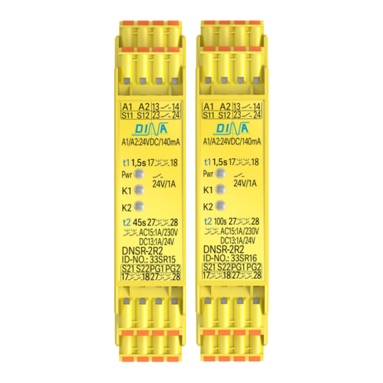
DNSR-2R2
Original Betriebsanleitung
Verwendung 33SR20
DNSR-2R2 ist geeignet zum Einsatz beispielsweise zur:
• Energietrennung von den Antrieben über den sicheren
rückfallverzögerten Kontakt 17
• Entriegelung von Schutzeinrichtungen über den
sicheren anzugsverzögerten Kontakt 27
• DNSR-2R2 kann in Sicherheitskreisen nach VDE 0113
Teil 1 eingesetzt werden mit maximal Kategorie 3/ PLd
nach DIN EN ISO 13849-1.
• DNSR-2R2 ist in 22.5mm Kunststoffgehäuse zur
Montage im Schaltschrak auf einer 35mm Hutschiene.
• Ein Anschlussplan ist an der Geräteseite.
Zeiteinstellung 33SR20
• Einstellung der Zeitverzögerung der Kontakte (15-16, 17-
18) und (25-26, 27-28) erfolgt frontseitig über je ein
Potentiometer.
• Eine Einstellung ist nur möglich bei gebrückten PG1/
PG2.
• Die Zeitübernahme erfolgt nur bei inaktiven S12 und
S22. (t1) für (15-16, 17-18), (t2) für (25-26, 27-28).
• Nach der Einstellung ist die Brücke zu entfernen.
• Die Einstellungen sind im Gerät gespeichert.
• Die Validierung der Zeit nach Einstellungen ist wichtig.
Anzeige und Verhalten im Fehlerfall 33SR20
24V DC
A1/A2:
ON
Verbunden
Nicht verbunden
PG1
PG2
Start
S11
S22
S21
S12
A1
S12
A1
S11
A1
S22
A1
S21
S11
S12
S11, S12
S22
S11, S12
S21
S11
S12 t2
S21,S22
S21, S22
S12
t2
S11 t2
S21,S22
S21,S22
S11
t2
Stand 30.08.2017
18.
S11
S12:
K1
S11
S12: K1 (t1
t1=0:
K1
, 17
Verbunden mit
S11/S12
S21/S22
X
S11
S12
S21
S11
S12
S22
S21
S12
12V
S21
S12
24V
S11
24V
S21
S11
S12
S22
S11
S12
S21
S11
S12
S21
S11
S12
S21
S12 12V
S21
S11
S12
S21
S11
S12
S21
S11
S12
S21
S22/S22
S11
S12
S21
S22/S22
Seite 9 von 16
Original Instruction Manual
Usage 33SR20
DNSR-2R2 is adapted to be used as example to:
• Turn off the power of the drives with safe contact
17
18.
• Enable the protection device with the safe contact
28.
27
28.
• DNSR-2R2 can be used in safety circuits according to
VDE 0113 part 1 with maximal category 3 / PLd
according to DIN EN ISO 13849-1.
• DNSR-2R2 is mounted in a 22.5mm synthetically
housing to be installed on a 35mm DIN rail.
• A connection plan is on the side of the unit.
Time adjustment 33SR20
• The adjustment of the time delay for the contacts
(15-16, 17-18 and 25-26, 27-28) happens in the front
panel via 2 Potentiometer.
• An adjustment is possible if PG1 is connected to PG2.
• The time storage happens if S12 and S22 are inactive.
(t1) is for (15-16, 17-18) (t2) is for (25-26, 27-28).
• After the adjustment PG1 and PG2 have to be unwired.
• The adjustments are stored in the unit.
• The time has to be validated after every adjustment.
Display and Performance on failure 33SR20
, 17
18, 15
16
S21
17
18 )
S21
t2=0:
18, 15
16
Connected
17-18
15-16
X
S22
15V
S22
S22
S22
24V
24V
S22
S22
S22
S22
S22
S11
S11
Date 2017-08-30
S22: K2
, 27
28, 25
S22: K2 (t2
27
K2
, 27
28, 25
Not connected ►Connected to
27-28
25-26
LED K1
0,5Hz
4Hz
1Hz
1Hz
1Hz
1Hz
Page 9 of 16
26
28),
26
LED K2
0,5Hz
1Hz
4Hz
4Hz
1Hz
4Hz
4Hz
