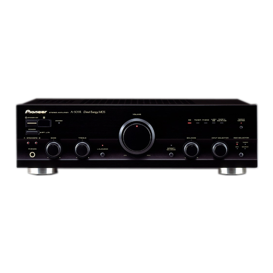
Pioneer A-509R Manuale di istruzioni per l'uso - Pagina 4
Sfoglia online o scarica il pdf Manuale di istruzioni per l'uso per Amplificatore Pioneer A-509R. Pioneer A-509R 12.
Anche per Pioneer A-509R: Manuale di servizio (30 pagine)

CONNECTIONS
CONNECTING THE SPEAKER CORDS
1. Strip off the vinyl covering and twist the tip of the wire core.
10mm
Twist the wire core.
2. Loosen the knob and insert the wire core into the terminal
hole.
3. Tighten the knob to fix the wire core in place.
2
1
NOTE:
Do not allow any of the cord conductors to protrude from the
terminals or touch any other conductors. Malfunctioning or break-
down may occur when conductors come into contact with each
other.
Speaker Impedance
When a speaker system is connected to only SPEAKERS A or
SPEAKERS B terminals, such speakers should have a rated im-
pedance in the range of 4
to 16
When speaker systems are connected to both the A and B termi-
nals, they should have a rated impedance in the range of 8
32
.
CONNECTING THE INPUT/OUTPUT CORDS
Connect the white plug to the left (L) channel, and the red plug
to the right (R) channel. Be sure to push the plugs in securely.
Left channel
White plug
R
4
<ARB7238>
3
.
to
L
Right channel
Red plug
REMOTE CONTROL CORD CONNECTIONS
By interconnecting the CONTROL jacks of Pioneer units with the
Î mark, the entire system can be operated with this remote
control unit, although some of the units (AM/FM tuner, compact
disc player, cassette deck, etc.) may not be equipped with re-
mote sensors. The entire system can be operated by the remote
control unit by connecting PIONEER stereo components to each
other using the control input (CONTROL IN) jack on each com-
ponent. Use the remote control cord supplied with the respec-
tive unit for the connection. As long as you connect "OUT" to
"IN", the connecting sequence is arbitrary. In the case of a unit
which has only an "IN" connector, however, connect it last.
1 Remote control unit
2 A-509R
3 Cassette deck
4 Compact disc player
5 AM/FM tuner
5
4
CONTROL
CONTROL
OUT
IN
OUT
IN
European model only:
AC OUTLET
[SWITCHED TOTAL 100 W MAX]
Power supplied through this outlet is turned on and off by
the amplifier's POWER switch. Total electrical power con-
sumption of connected equipment should not exceed 100 W.
AC OUTLET
SWITCHED
100W MAX
NOTES:
¶ This unit should be disconnected by removing the
power plug from the wall socket when not in regular
use, e.g. when on vacation.
¶ Do not connect appliances with high power consump-
tion such as heaters, irons, or television sets to this AC
OUTLET in order to avoid overheating and fire risk. This
can also cause the receiver to malfunction.
CAUTION:
DO NOT CONNECT A MONITOR OR TV SET TO
THE AC OUTLET.
3
2
1
CONTROL
OUT
CONTROL
OUT
IN
