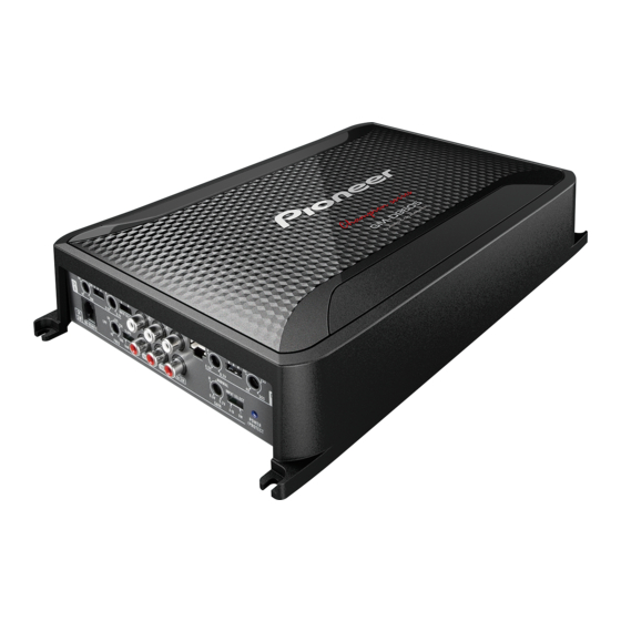
Pioneer GM-D9605 Manuale di servizio - Pagina 7
Sfoglia online o scarica il pdf Manuale di servizio per Amplificatore Pioneer GM-D9605. Pioneer GM-D9605 29. Bridgeable four-channel power amplifier

4. BLOCK DIAGRAM
A
MAIN PCBA
RCA input(AL)
Isolator
RCA input(AR)
Isolator
RCA input(BL)
Isolator
RCA input(BR)
Isolator
Mixing Amp
Speaker level input
ATT
(AL/AR/BL/BR)
AB or SW
RCA input(SW_L)
Isolator
RCA input(SW_R)
Isolator
Bass Boost RCU
DC +/- 15
Buffer amp with gain
Gain volume
Buffer amp with gain
2CH or 4CH
Buffer amp with gain
Gain volume
Buffer amp with gain
Gain volume
Buffer Amp
Bass Boost
Mixing Amp
DC - 48V
DC - 16V
DC +/ - 5V
DC +/ - 15V
DC +/- 60V, DC -48V, DC +/ -5V
LPF/HPF/Pass
LPF/HPF/Pass
Driver IC (IRS2093M)
of Power AMP
LPF/HPF/Pass
Invertor
LPF/HPF/Pass
Invertor
DC +/- 28V, DC -16V, DC +/ -5V
LPF
ATT
Driver IC (IRS2092S)
-12/ -24dB
by
of Power AMP
thermal
detector
DC +/- 60V
Trans former
MOSFET(IRF3205)
DC +/ - 28V
LPF
LPF
MOSFET(IRF6775M)
of output
LPF
LPF
Output current detect
MOSFET(IRFB4227)
LPF
of output
Output current detect
Output DC detect
Over voltage detect
Power on/off
Driver IC (TL494)
of DCDC
Thermal detect
Speaker
output
Bu (14.4V)
System control
GND
