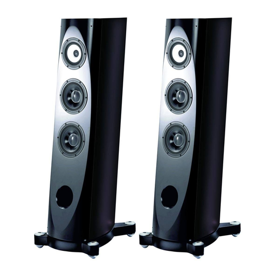
Pioneer S-1EX Manuale di servizio - Pagina 8
Sfoglia online o scarica il pdf Manuale di servizio per Sistema di altoparlanti Pioneer S-1EX. Pioneer S-1EX 12. Ex series
Anche per Pioneer S-1EX: Manuale di istruzioni per l'uso (28 pagine), Opuscolo e specifiche (16 pagine)

1
2. FOR PRECAUTION OF REASSEMBLY AND DISASSEMBLY
2.1 GRILLE
A
How to disassemble
1 Loosen the finishing screws. Then remove the grille.
Finishing Screws
B
Note 1:
You may remove the fastening screws if they impede
disassembly.
C
2.2 SPEAKER UNIT
For better audio quality, the receptacle terminals and terminal fittings of the speaker unit are soldered.
Two people are required for servicing of this speaker unit: one to hold the removed unit and another to
solder.
Tools to be used
• Hexagonal wrench (4 mm): GGK1024
• Soldering gun: GGK1069
D
• Lead-free solder: GYP1006
• The woofer is attached to the baffle board with 6
hexagon-socket screws from the outside.
When disassembling, remove all these screws, pull out the
woofer, then remove the solder to disconnect the cords.
When reattaching, after connecting the cords, solder the
terminals for the woofer then place the woofer so that the
terminal board comes to the lower side.
Upper side
E
Upper woofer
Terminal size: Large
Upper side
Lower woofer
F
Terminal size: Large
8
1
2
Terminal size: Extra large
: White with Black line
White tape
Long cord
: White
Terminal size: Extra large
: White with Black line
White tape
Short cord
: White
2
3
How to reassemble
1 Insert the supplied fastening screws into the screw holes at
the four corners of the speaker front.
2 Place the grille with the badge located at the lower part,
aligning the 4 holes of the grille with the fastening screws
inserted in Step 1.
3 Tighten the supplied finishing screws into the fastening
screws to secure the grille.
Finishing Screws
Note 2:
Do not use a flathead screwdriver or a hexagonal wrench to
tighten the screws. Securing the screws too tightly may
damage the cabinet.
• The midrange and tweeter are integrated into a coaxial
unit. This coaxial-unit speaker is attached to the baffle
board with 6 hexagon-socket screws from the outside.
When disassembling, remove all these screws, pull out
the coaxial-unit speaker, then remove the solder to
disconnect the cords.
When reattaching, connect the cord with black tape to the
tweeter and the cord with white tape to the midrange then
solder the terminals. Place the coaxial unit so that the
terminal board of the midrange comes to the lower side
then turn it counterclockwise slightly to secure it.
Terminal board
of the tweeter
Upper side
Coaxial unit
Terminal board
of the midrange
S-1EX
3
4
Fastening Screws
: White with Black line
Terminal size:
Black tape
Large
Terminal size:
Small
: White
: White with Black line
Terminal size:
White tape
Extra large
Terminal size:
Large
: White
4
