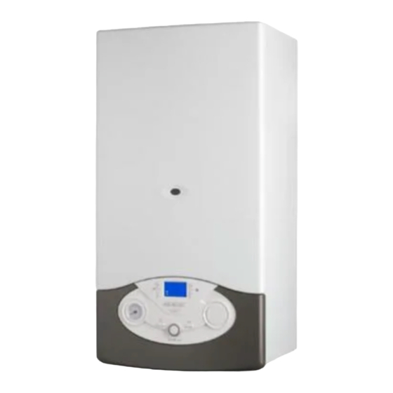
Ariston CLAS EVO SYSTEM 24 CF Istruzioni per la manutenzione - Pagina 22
Sfoglia online o scarica il pdf Istruzioni per la manutenzione per Caldaia Ariston CLAS EVO SYSTEM 24 CF. Ariston CLAS EVO SYSTEM 24 CF 44. Wall-hung gas boiler
Anche per Ariston CLAS EVO SYSTEM 24 CF: Manuale d'uso (13 pagine), Manuale del prodotto (48 pagine)

messa in funzione
Controllo della potenza massima riscaldamento assoluta
(
SOLO IN CASO DI CAMBIO GAS O SOSTITUZIONE SCHEDA
Per controllare/modifi care la potenza massima riscaldamento
assoluta accedere alla valvola gas e procedere come segue:
1. Allentare la vite "2" (fi g.b) ed inserire il tubo di raccordo del
manometro nella presa di pressione.
2. Scollegare il tubetto di compensazione della camera aria.
3. Mettere la caldaia in funzione alla potenza massima riscaldamento
attivando la "funzione spazzacamino".
Premere il tasto
per 10 secondi, sul display viene visualizzato
TEST ed il simbolo
.
La pressione di alimentazione deve corrispondere a quella
prevista nella Tabella Riepilogativa Gas per il tipo di gas per cui la
caldaia è predisposta. Se non dovesse corrispondere accedere al
menu 2/sottomenu 3/parametro 0 e modifi care il valore fi no al
raggiungimento della pressione indicata nella Tabella riepilogativa
Gas.
4. Al termine del controllo stringere la vite "2" e controllarne la
tenuta.
5. La funzione spazzacamino si disattiva automaticamente dopo 10
minuti o premendo il tasto
La tabella indica la relazione esistente tra la pressione del gas al
bruciatore e la potenza della caldaia in modalità riscaldamento.
Pressione Gas Riscaldamento / Heating Gas Pressure
Gas
Potenza termica / Heat output (kW)
G20
mbar
Parametro / Parameter 2 3 1
G30
mbar
Parametro / Parameter 2 3 1
G31
mbar
Parametro / Parameter 2 3 1
Gas
Potenza termica / Heat output (kW)
G20
mbar
Parametro / Parameter 2 3 1
G30
mbar
Parametro / Parameter 2 3 1
G31
mbar
Parametro / Parameter 2 3 1
Cambio Gas
La caldaia può essere trasformata per uso da gas metano (G20) a Gas
Liquido (G30 - G31) o viceversa a cura di un Tecnico Qualifi cato con
l'utilizzo dell'apposito Kit.
Le operazioni da svolgere sono le seguenti:
1. togliere tensione all'apparecchio
2. chiudere il rubinetto del gas
3. scollegare elettricamente la caldaia
4. accedere alla camera di combustione, come indicato nel
paragrafo "Istruzioni per l'apertura della mantellatura ed
ispezione dell'interno"
5. sostituire gli ugelli ed applicare le etichette come indicato nel
foglio istruzioni del Kit.
6. verifi care la tenuta gas
7. mettere in funzione l'apparecchio
8. provvedere alla regolazione gas vedi paragrafo ("Verifi ca delle
regolazioni gas"):
- controllo della potenza massima sanitario
- controllo della potenza minima
- controllo della potenza massima riscaldamento assoluta
- regolazione della massima potenza riscaldamento regolabile
- controllo della lenta accensione
- regolazione del ritardo di accensione in riscaldamento
9. eseguire l'analisi della combustione.
22
)
.
commissioning
Checking maximum absolute heating power
(
ONLY IN CASE OF GAS CHANGE OR P
To check/modify the maximum absolute heating power, access
the gas valve and proceed as follows:
1. Loosen screw "2" (Fig. b) and insert the pressure gauge
connection pipe into the pipe tap.
2. Disconnect the air chamber compensation tube.
3. Switch the boiler on at maximum heating power, enabling the
"chimney sweep" function.
Press the
button for 10 seconds, on the display appear
TEST and the icon
.
The supply pressure should correspond to the value shown in
the "Gas Settings" table according to the type of gas for which
the boiler is designed. If it does not correspond, access menu
2/sub menu 3/parameter 0 and modify the value until the
pressure indicated in the Gas Table has been reached.
4. When the check is complete, tighten screw "2" and make sure it
is securely in place.
5. The "chimney sweep" function is deactivated either automatically
after 10 minutes or when the E
The table indicate the existing relationship between the gas pressure
at the burner and the boiler power level in heating mode.
9,9
12
14
16
2,2
3,2
4,4
5,7
0
39
44
49
5,5
8,0
11,0
14,3
0
54
61
67
6,0
8,8
12,0
15,6
0
56
63
70
11,2
14
16
18
2,3
3,6
4,7
5,9
0
37
41
45
5,3
8,3
8,9
13,7
0
51
58
63
7,5
11,7
15,3
19,4
0
59
66
72
Gas Changeover
The boiler may be adjusted so that it may be used with Liquid Gas
(G30-G31) instead of methane gas (G20) or vice-versa.
The adjustment must be performed by a Qualifi ed Technician using
the special Kit.
The following procedures must be completed:
1. Switch off the electrical supply to the appliance.
2. Shut off the gas valve.
3. Disconnect the electrical connections to the boiler.
4. Access to the combustion chamber, as indicated in the paragraph
"Instructions for opening the casing and performing an internal
inspection".
5. Replace the nozzles and attach the labels as indicated in the
instruction sheet supplied with the Kit.
6. Check that all connections are gas-tight.
7. Start up the boiler.
8. Perform the gas adjustment (refer to the paragraph "Checking
the gas adjustment"):
-
check the domestic water maximum power
-
check the minimum power
-
check the maximum absolute heating power
-
adjust the maximum adjustable heating power
-
check the slow ignition
-
adjust the heating ignition delay
9. Carry out the combustion analysis.
.
.
.
)
C
B
REPLACEMENT
button is pressed.
SC
18
20
22
7,2
7,6
9,1
54
55
59
18,1
18,9
22,9
73
75
80
19,8
23,5
28,5
76
80
87
20
24
25
7,3
9,0
9,7
50
55
57
16,9
22,0
23,8
68
78
80
23,9
28,3
30,7
79
86
89
23,7
10,6
64
26,5
84
33,0
93
26,7
11,1
62
27,2
85
35,0
97
