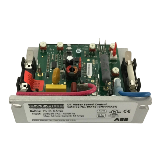
ABB Baldor BC141 Manuale d'installazione e d'uso - Pagina 18
Sfoglia online o scarica il pdf Manuale d'installazione e d'uso per Unità di controllo ABB Baldor BC141. ABB Baldor BC141 20. Dc control

3. Run the motor with the maximum load and adjust the IR Trimpot so that the motor speed under
load equals the unloaded speed recorded in step 2.
4. Remove the load and recheck the RPMs.
5. If the unloaded RPM has changed, repeat steps 2 - 4 for more exact regulation. The control is now
compensated to provide minimal speed change due to changing loads.
Operation
Set the AC Line Switch to the ON position. Observe that the Pilot Light illuminates. Gradually increase
the Main Speed Potentiometer. The motor should smoothly come up to the desired speed and remain
stable.
Troubleshooting
The control has LEDs to display the control's operational status.
Power On (PWR ON) LED and Pilot Light
When the AC power is applied to the control and the On/Off AC Line Switch is set ON, the PWR ON
LED, on the PC board, will illuminate green and the Pilot Light, on the front cover, will illuminate
orange.
Current Limit (CL) LED
The CL LED will illuminate red when the motor is overloaded, indicating that the current limit set point
has been reached (set by the CL Trimpot).
Table 2-4 provides information on symptoms, possible causes, and the suggested corrective action for
controls without optional forward-brake-reverse switch installed.
Table 2-4 Troubleshooting Guide (without Optional Forward-Brake-Reverse Switch)
Symptom
Motor is not running and
Pilot Light not illuminated.
Motor does not run and
Pilot Light is illuminated.
Motor hums, runs at very
low speed, or slows down
substantially when loaded.
Motor continues to run with
Main Speed Potentiometer
set fully counterclockwise.
Motor runs in wrong
direction.
MN704
Possible Cause
On/Off AC Line Switch in Off
Position.
Blown Line fuse.
Defective On/Off AC Line Switch,
Main Speed Potentiometer set fully
counterclockwise.
Defective motor.
Plug-In Horsepower Resistor® not
installed.
Blown Armature Fuse.
CL Trimpot set fully
counterclockwise.
Low AC line input voltage.
MIN speed trimpot set higher than
0% of base speed.
IR Comp trimpot set too high.
Motor armature leads are reversed.
Suggested Corrective Action
Set On/Off Switch to On Position.
Replace Line Fuse.
Replace On/Off AC Line Switch.
Rotate Main Speed potentiometer clockwise.
Check for defective motor, worn brushes, etc.
Replace motor, if necessary.
Install the correct Plug-In Horsepower
Resistor®.
Replace Armature Fuse.
Set CL Trimpot
Check AC line input voltage.
Readjust the MIN Trimpot.
Readjust the IR Trimpot.
Reconnect motor armature leads.
2-11
