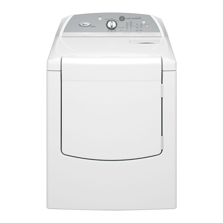
Whirlpool WGD6400SW0 Scheda tecnica - Pagina 11
Sfoglia online o scarica il pdf Scheda tecnica per Asciugatrice Whirlpool WGD6400SW0. Whirlpool WGD6400SW0 12. 29" gas dryer
Anche per Whirlpool WGD6400SW0: Elenco delle parti (8 pagine), Manuale di avvio rapido (6 pagine)

TECH SHEET - DO NOT DISCARD
ACCESSING & REMOVING
THE ELECTRONIC
ASSEMBLIES
There are two electronic assemblies; the
machine control electronics and the user
interface electronics. See figures 15
and 16.
Back Cover Locking Tabs
3 Screws
P5
Ribbon
Cable
Machine Control
Electronics
User Interface
Assembly
Assembly Back Cover
Figure 15. Locate the electronic
assemblies.
1. Unplug dryer or disconnect power.
2. Remove two screws from the rear of
the console assembly. Pull console
towards front of dryer to hinge open
and/or remove console.
Removing the Machine Control
Electronics
3. Remove the wire connections to the
machine control assembly.
4. Remove the one screw holding the
machine control assembly to the
metal bracket. See figure 15.
5. Push in on the tab located on the
back of the machine control to slide
it off the bracket.
Removing the User Interface
Assembly
3. Remove the wire connections from
the user interface assembly,
including the P5 ribbon cable. See
figure 15.
4. Remove the cycle selector knob
from the front of the console by
firmly pulling on it or carefully prying
straight upward.
5. The user interface assembly is held
to the console insert panel by three
screws and two locking tabs. After
the screws are removed, lift each of
the locking tabs to remove the back
cover of the user interface assembly.
See figure 15.
FOR SERVICE TECHNICIAN'S USE ONLY
N.O.
Heater
Black
Relay 1
Figure 16. Machine control electronics.
Screw
Metal Bracket
6. Remove the cycle selector switch
from the user interface assembly
opening by lifting the locking tab on
the cycle selector switch and turning
the selector switch in a
counterclockwise direction. See
figure 17.
Cycle Selector
Switch
Locking
Figure 17. Gently apply pressure to
locking tabs to release the user interface
assembly.
7. Locking tabs located at the bottom
of the console insert panel secure
the user interface assembly to the
console insert panel. Using a
flat-blade screwdriver, gently apply
pressure to the locking tabs to
release the user interface assembly.
See figure 17.
Reinstalling the Electronic
Assemblies
Refer to preceding removal sections and
replace in reverse order.
NOTE: When replacing the cycle selector
switch, make sure that the shaft is
positioned through the center of the shaft
seal that is captive between the decorative
overlay and the console panel insert.
COM
Motor
Blue
Black
Red
Relay
P9
1
5
Black-White
Tan
White
Green-Yellow
1
P8
Brown
Tabs
User Interface
Assembly
Yellow-Red
Red-White
Open
3
1
NOTE: When reconnecting wire
connections, be sure to route the user
interface wires beneath the retainer clips
on the user interface back cover.
REMOVING THE BACK
PANEL
1. Unplug dryer or disconnect power.
2. Remove the cover plate screw and
cover plate. See figure 18.
3. Remove the eight rear screws from the
back panel, then remove panel.
Cover Plate Screw
Cover Plate
Figure 18. Remove screws.
PART NO. W10054160
PAGE 11
1
1
P13
P3
P5
8
1
P2
3
P14
1
6
P4
1
Black
Red-White
