Whirlpool AKR 951 Scheda di installazione - Pagina 20
Sfoglia online o scarica il pdf Scheda di installazione per Cappa di ventilazione Whirlpool AKR 951. Whirlpool AKR 951 20. 100cm island curved glass cooker hood, akr 951/1 ix
Anche per Whirlpool AKR 951: Manuale di istruzioni per l'uso (9 pagine), Scheda di installazione (10 pagine)

31833159.fm Page 20 Friday, April 1, 2005 6:35 PM
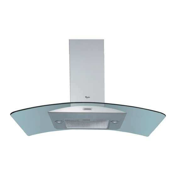
AKR 951 - AKR 953 - AKR 960 - AKR 810
1. Control panel.
2. Grease filter.
3. Halogen bulbs.
4. Steam deflector.
5. Telescopic flue.
To clean the grease filter
Wash the grease filter at least once a month.
1. Disconnect the electrical power supply
2. Remove the grease filters - Fig. 2: pull the spring
release handle (f) downwards, then remove the
filter.
3. After cleaning the grease filter refit in reverse
order, making sure the entire extraction surface is
covered.
Carbon filter Fitting and Maintenance
Fitting the carbon filter:
1. Disconnect the electrical power supply.
2. Remove the grease filter (f - Fig. 2).
3. Turn the side knobs 90° and then remove the
filter holder (g - Fig. 3).
4. Fit the carbon filter (h - Fig. 3) in the filter holder
(i - Fig. 3).
5. Refit the filter holder and secure it to the hood
with the screw (g - Fig. 3).
6. Refit the grease filter.
Carbon filter maintenance:
Unlike traditional carbon filters, this carbon filter can
be washed and reactivated.
With normal hood use, the filter should be cleaned
once a month. The best way to clean the filter is in a
dishwasher at the highest temperature possible, using
a normal dishwasher detergent. To avoid particles of
food or dirt settling on the filter during washing and
giving rise to unpleasant smells, it is advisable to wash
the filter on its own. After washing, dry the filter in the
oven at 100° C for 10 minutes to reactivate it.
The filter will retain its odour-absorbing capacity for
three years, after which it must be replaced.
Replacing bulbs
1. Disconnect the electrical power supply.
2. Use a small screwdriver or any other suitable tool
to prise off (m-Fig. 4) the lamp cover (p-Fig. 4).
3. Remove the burnt-out bulb.
Replace using 20 W max halogen bulbs only,
making sure not to touch them with your hands.
4. Close the lighting unit (snap-close).
5019 318 33159
PRODUCT SHEET
CONTROL PANEL
A.
B.
B+C.Speed 2 selector switch
B+D.Speed 3 selector switch
PL
CZ
SK
H RUS BG
Light ON/OFF switch.
ON/OFF and speed 1 selector switch
(small amount of steam and fumes).
(medium amount of steam and fumes).
(large amount of steam and fumes).
RO
GB
Fig. 1
Fig. 2
Fig. 3
Fig. 4
