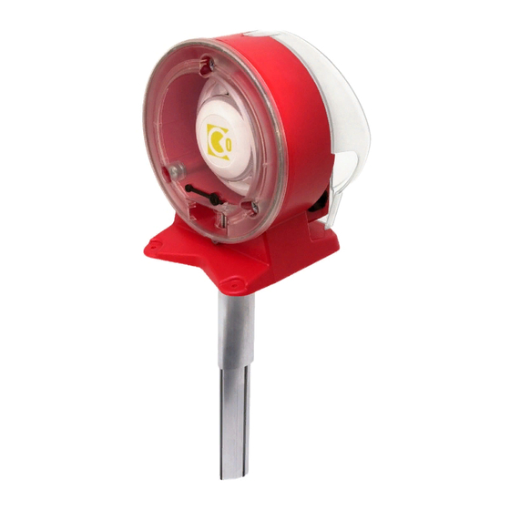
CALECTRO Uniguard Superflow UG-3-J Istruzioni per l'installazione - Pagina 2
Sfoglia online o scarica il pdf Istruzioni per l'installazione per Allarme fumo CALECTRO Uniguard Superflow UG-3-J. CALECTRO Uniguard Superflow UG-3-J 4.
Anche per CALECTRO Uniguard Superflow UG-3-J: Istruzioni per l'installazione (5 pagine), Istruzioni per l'installazione (4 pagine)

Borra hål i kanalen:
• Håltagning utan monteringsbeslag, ø 38 mm.
• Håltagning med monteringsbeslag och/eller venturirör
med monterad fläkt, ø 51 mm (se punkt 10).
• Mät ventilationskanalens diameter.
• Kapa eventuellt röret.
• Röret bör täcka minst 90% av
kanalens diameter.
OBS! Se även punkt 8.
• Sätt i ändpluggen.
• Träd på tätningen på röret.
• För in röret i botten på Uniguard.
• Lås fast röret med stoppskruven.
• Montera röret och detektorn på kanalen.
• Fäst Uniguard på 3 punkter vid pilarnas
markering.
OBS VIKTIGT!
Riktningspilarna (se Uniguardfotens
form eller ovansidan huset) skall ha
samma riktning som luftflödet i kanalen.
Flödesindikator och fläktrör*.
Uniguard är försedd med en indikator, en
plasttunga, som – när detektorn är rätt
installerad – svängs ut av luftströmmen.
OBS!
Rör sig inte indikatorn alls bör man
överväga en omplacering av detektorn,
alternativt montera ett s.k. fläktrör*.
Vid montering av fläktrör används alltid ett
monteringsbeslag.
* Fläktrör är ett standard venturirör med hjälpfläkt,
vilken kräver separat 24 VAC/DC matning.
Elinstallation.
• Öppna locket över kopplingshuset genom
att lyfta på snäpplåset.
• För in kabeln genom valfri Klikseal
kabelgenomföring.
Används annan typ av genomföring
demonteras de förmonterade genom
att först trycka igenom ena sidan och
därefter den andra (1-2).
1
Kapa EJ denna ände!
Do NOT cut this end!
3
Stoppskruv.
Locking screw.
5
Flödesindikator.
Flow indicator.
Venturirör med hjälpfläkt.
Venturi pipe with booster fan.
6
Snäpplås.
Snap locking.
(1)
(2)
Drill a hole in the duct:
• Without mounting bracket, ø 38 mm.
• With mounting bracket and/or venturi pipe with
booster fan, ø 51 mm (see para 10).
2
• Measure the diameter of the duct.
• Shorten the pipe, if necessary.
• The pipe should penetrate at least 90%
of the width of the duct.
NOTE! See para 8.
• Insert the end plug.
Ändplugg.
End plugg.
• Mount the black gasket on the pipe.
• Insert the pipe into the bottom of the
Uniguard.
• Secure the pipe with the locking screw.
Tätning.
Gasket.
4
• Mount the pipe and the detector on the duct.
• Secure the bottom of the Uniguard with
the 3 screws, positions marked.
NOTE - IMPORTANT!
The air flow direction arrows (see
the Uniguard foot's shape or on the
housing top) must have the same
direction as the air flow in the duct.
Flow indicator and booster fan pipe*.
The Uniguard is supplied with an indicator,
a plastic "tongue", which – when the
detector is correctly installed – is bent
outwards due to the airflow.
NOTE!
If the indicator does not move, you should
consider a new mounting positioning of the
Uniguard or install a booster fan venturi pipe.
With installation of a booster fan venturi pipe
a mounting bracket is always used.
* A booster fan pipe is a standard venturi pipe including a
booster fan, which needs separate 24 VAC/DC supply.
Electrical installation.
• Remove the cover over the printed circuit
board by opening the snap locking.
• Enter the cable through one of the
Klikseal glands.
When using another type of cable gland
dismount the ones already installed by
first pressing one side through the hole
and then the other one (1-2).
