CALEFFI BIOMASS OPTIMISER 1522 Series Manuale di installazione e messa in servizio - Pagina 5
Sfoglia online o scarica il pdf Manuale di installazione e messa in servizio per Controllore CALEFFI BIOMASS OPTIMISER 1522 Series. CALEFFI BIOMASS OPTIMISER 1522 Series 12. Digital regulator for heating systems with solid fuel generator

Available programs
OPTIMISER
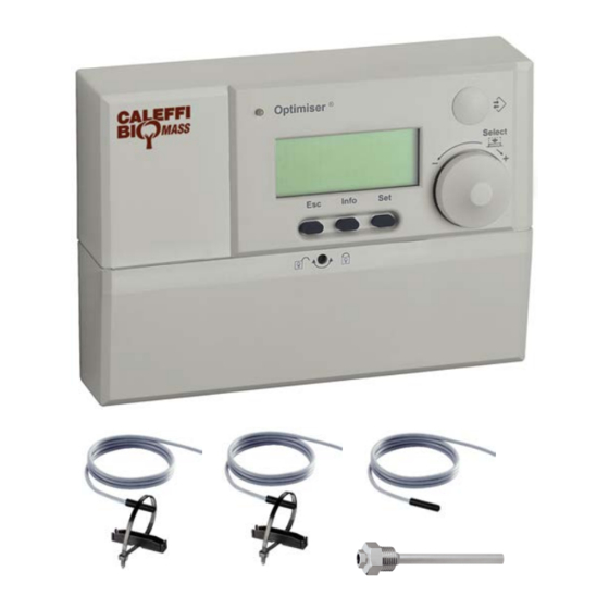
digital regulator code 152200 can be used in accordance with 6 different system configurations (programs), comprising a basic
®
factory-set configuration and 5 optional configurations selectable by means of the table shown below and activatable by means of the dipswitches
on the regulator. To access the dipswitches open the cover under the display. The regulator is supplied with the factory settings and probes
required to perform basic program 4.
Program
configuration
Heating + management of
4
inertial water storage in
(basic factory set
parallel on the heating
program)
Heating and domestic hot water
with storage + management of
5
inertial water storage in parallel
on the heating system*
Heating and instantaneous
domestic hot water + management
6
of inertial water storage in parallel
on the heating system*
Heating with direct inertial
water storage with tank-in-
7
tank domestic hot water
production, solar system
Heating with direct inertial
water storage, domestic hot
8
water storage integrated with
Heating with direct inertial water
storage integrated with solar
9
system, instantaneous domestic
hot water production
Programs 1,2 and 3 (not listed in the table but however available) are functionally equivalent to programs 7,8 and 9 respectively but without
thermal solar components. For specific setting (dipswitches and probes to be used) please see instruction sheet 28169 (www.caleffi.com).
NOTE The probes are all of the NTC type (grey cable) except for probe Sol1 utilised by solar programs 7, 8 and 9, which
is type Pt1000 with
red cable.
* refer to operating logic of program "management of inertial water storage in parallel on the heating system" on the next page.
Location of cable glands
When making the electrical connections, observe the following sequence for wiring the terminal board.
- If the regulator is to be wall mounted with the consequent use of the supplied cable glands and downward cable outlet, regulations require that just
one cable can transit through each hole of the cable gland, therefore a maximum of 6 high voltage cables and 6 low voltage cables can be utilised.
It is therefore recommended to comply with the following table of connections and use two additional junction boxes complete with suitable inlet and
outlet cable glands, in accordance with the diagram given. The earth connection must be made in the junction box.
- If the regulator is installed in an electrical cabinet, the cable outlet must be via the openings at the rear of the unit, always keeping high and
low voltage cables separated. The earth connection must be made in the electrical cabinet.
HIGH VOLTAGE
HIGH VOLTAGE
JUNCTION BOX
Description
S1
system*
S1
S1
S1
S1
solar system
S1
LOW VOLTAGE
Domestic priority diverter valve V2 or domestic priority
Valve V5 for loading the inertial water storage in
Probe S5 or solar water storage probe Sol2
LOW VOLTAGE
JUNCTION BOX
Room thermostat TA or adjustment thermostat TR contact
Domestic water storage probe S2 or probe S3 on
Probes utilised
-
-
S4
S2
-
S4
S3
-
S4
-
Sol 1
Sol 2
S2
Sol 1
Sol 2
S3
Sol 1
Sol 2
Electric connection
Electric supply
Pump P1
Pump P2
Gas generator contact C
Solid fuel generator contact K
Diverter valve V1
Diverter valve V4 to optional dissipator
diverter valve V3
SOLARINCAL type diverter valve
parallel or solar circuit pump Psol
Probe S1
Probe S4 or solar collector probe Sol1
domestic heat exchanger outlet
Flow switch F
5
Position of
Software
program
code
selectors
(dipswitches)
ON
S5
PR83
1 2 3 4
ON
S5
PR84
1 2 3 4
ON
S5
PR85
1 2 3 4
ON
-
PR86
1 2 3 4
ON
-
PR87
1 2 3 4
ON
-
PR88
1 2 3 4
Recommended electrical cable:
nr. wires for cross-section
2x1,5 mm
2
4x1 mm
2
4x1 mm
2
4x1 mm
2
6x1 mm
2
2x1 mm
2
2x0,75 mm
2
2x0,75 mm
2
2x0,75 mm
2
2x1 mm
2
2x0,75 mm
2
2x0,75 mm
2
Hydraulic
diagram
on page
7
8
9
10
11
12
Dedicated
cable gland
A
B
C
D
E
F
G
H
I
L
M
N
