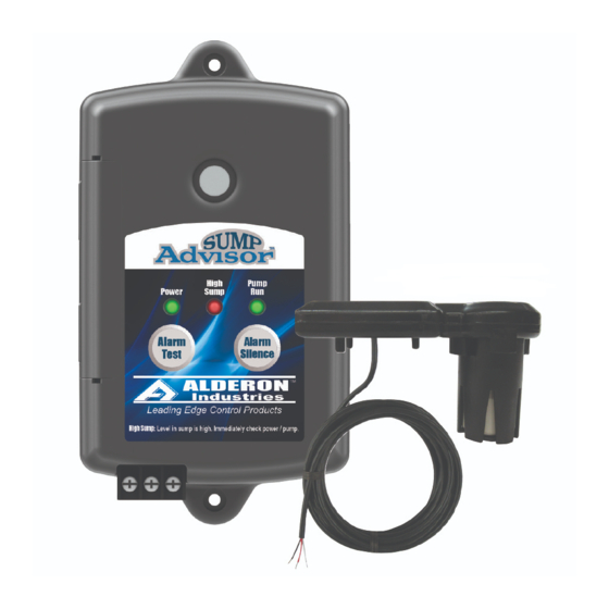
Alderon Industries Sump Advisor 2000558 Manuale di avvio rapido - Pagina 3
Sfoglia online o scarica il pdf Manuale di avvio rapido per Sistema di sicurezza Alderon Industries Sump Advisor 2000558. Alderon Industries Sump Advisor 2000558 4. 2-zone alarm and sensor

Step 6: VertiMAC™ Pump Switch
Determine the pump differential and move the rubber grommet on the
actuator rod to achieve the desired range. The maximum differential is
six inches (6.0") and minimum differential is one and a half inches (1.5").
(Pump Activated)
Maximum (6.0")
Step 8: Connecting Pump Switch Power
PIGGYBACK PLUG MODELS:
1) Plug the male end of the piggyback plug on the VertiMAC™ pump
switch power cable into a standard wall outlet or power receptacle
that matches the voltage of the pump switch (8A).
2) Plug the male end of the pump power cable into the female end of
the piggyback plug on the VertiMAC™ pump switch power cable
(8B).
VertiMAC™ Pump Switch
Piggyback Plug
Power Cable
8A
8B
BARE LEAD MODELS:
1) Connect bare lead wires from the VertiMAC™ pump switch power
cable to terminal inputs in a junction box as shown in the diagram.
WARNING: In 240VAC installations, one side of the line going to the load is
always HOT. This condition exists if the switch is on or off. Install double pole
disconnect on all 240VAC circuits.
120/240 VAC
G L2/N L1
POWER SOURCE
G
LOAD
G L2/N L1
(sold separately)
Minimum (1.5")
(Pump Deactivated)
(Pump Deactivated)
(120VAC Example Shown)
Pump
Power Cable
WIRE USING
JUNCTION BOX
BLACK
WHITE
Step 7: Mounting Pump Switch
Attach the pipe clamp to pipe at
the approximate mounting level
and tighten using the fastener nut.
Make sure to keep all cables and
wires away from the float while
mounting.
Note: Do not completely secure pipe clamp
and VertiMAC™ pump switch to the pipe
until the off level has been determined.
After the off level has been set, check to
make sure level is above the intake to the
pump to prevent dry cycling. Refer to the
instructions that came with the pump for
complete operation. Once the pump switch
is in the final mounting location, securely
fasten the pipe clamp and VertiMAC™
pump switch to maintain an accurate
pumping range.
CAUTION: The VertiMAC™ pump switch
MUST be mounted in the vertical position.
Mounting the pump switch at an angle will
result in the switch not functioning properly.
Perform a quick test by lifting the float up
and down to ensure the switch is working.
Do not connect power until the installation of
both the Sump Advisor™ sensor and Sump
Advisor™ alarm panel are completed.
Step 9: Connecting Alarm Panel Power
POWER CORD MODEL ONLY:
The alarm panel should be installed, wired to the Sump Advisor™
sensor, and the power outlet (120VAC, 50/60 Hz) is within five feet (5')
of the alarm panel. The power outlet should be on a separate circuit
breaker from any other device and not on a switched receptacle to
maintain power integrity. See step 2 and step 3 mounting alarm panel.
Step 10: System Check
Prior to testing, make sure the installation process is complete. Check
to make sure there are no wires to interfere with the operation of the
float on the VertiMAC™ pump switch, the VertiMAC™ pump switch has
been connected to a power supply, the Sump Advisor™ sensor has
been wired to the Sump Advisor™ alarm panel, and the green power
LED is illuminated on the Sump Advisor™ alarm panel. For the quick
test of the pump switch, sensor, and alarm panel see steps 11 and 12.
