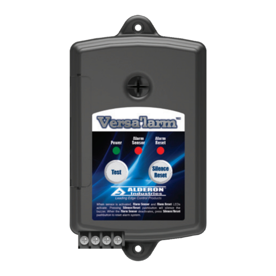
Alderon Industries Versa'larm 8125 Manuale di funzionamento, manutenzione e installazione - Pagina 3
Sfoglia online o scarica il pdf Manuale di funzionamento, manutenzione e installazione per Sistema di sicurezza Alderon Industries Versa'larm 8125. Alderon Industries Versa'larm 8125 4.

Versa'larm
Part Numbers - 8124 (alarm panel only) and 8125
Manual Alarm Reset
Operation, Maintenance and Installation Manual
Installation of the Alarm Panel Continued
4. After the access cover has been removed from the alarm panel (Fig. 10), use a needle nose pliers (not included) to
remove the desired "break away tabs" from the access cover, lightly pull and twist off tab(s) (Fig. 11). Replace the access
cover and run wire(s) through the knockout(s) (Fig. 12).
(Fig. 10)
5. Make note of the alarm condition(s) you are monitoring and keep them near the alarm panel.
6. Connect the normally open switch (rated 9 VDC, 200mA Minimum) such as a float switch, water sensor, or sump probe
sensor to Terminals C and 1 on the terminal block of the alarm panel (Fig. 13). Place the switch in the desired monitoring
location where water needs to be detected.
7. The alarm panel is also equipped with a set of normally open alarm dry contacts rated at 24 VDC/AC, 100mA Maximum,
which are connected to Terminals 2 and 3 on the terminal block of the alarm panel (Fig. 13).
8. Plug the alarm panel power supply into a 120 VAC, 50/60 Hz standard
wall outlet and the green power LED should illuminate (Fig. 14).
Alarm Systems
Control Panels
Alderon Industries - Hawley, MN | 218.483.3034 | [email protected] | alderonind.com
™
(Fig. 11)
(Fig. 13)
Normally Open Dry Contact
Switch/Sensor (C and 1)
Float Switches
Normally Open Dry Contacts
(2 and 3)
Leak Detection Systems
(Fig. 12)
(Fig. 14)
5 ft. Max
P/N: IOM0000027
3 of 4
